Quick-connect ballast testing and monitoring method and apparatus

a technology for fluorescent lamps and ballasts, which is applied in the direction of discharge tube testing, electric lighting sources, instruments, etc., can solve the problems of difficult for even an electrician to determine whether an inoperable system is inoperable, and troubleshooting an inoperable system is often achieved by trial and error, and achieves the effect of quick connection

Inactive Publication Date: 2005-12-06
SCHRIEFER JAY R
View PDF16 Cites 9 Cited by
  • Summary
  • Abstract
  • Description
  • Claims
  • Application Information

AI Technical Summary

Benefits of technology

[0010]Still another object of this invention is to provide a method and apparatus, as aforesaid, which can determine whether a fluorescent lamp or ballast itself is inoperable.

Problems solved by technology

The complexities of fluorescent light assemblies with a ballast make it difficult even for an electrician to determine whether an inoperable system is due to the ballast, a lamp, or an overall lack of electrical power.
In the past, troubleshooting an inoperable system was often accomplished by trial and error, i.e. by replacing a bulb or ballast without really knowing what the source of the problem was.

Method used


Image

  • Quick-connect ballast testing and monitoring method and apparatus
  • Quick-connect ballast testing and monitoring method and apparatus
  • Quick-connect ballast testing and monitoring method and apparatus

Examples


Embodiment Construction

[0020]A quick-connect ballast testing and monitoring apparatus and method will now be described in detail with reference to FIGS. 1 through 6 of the accompanying drawings.

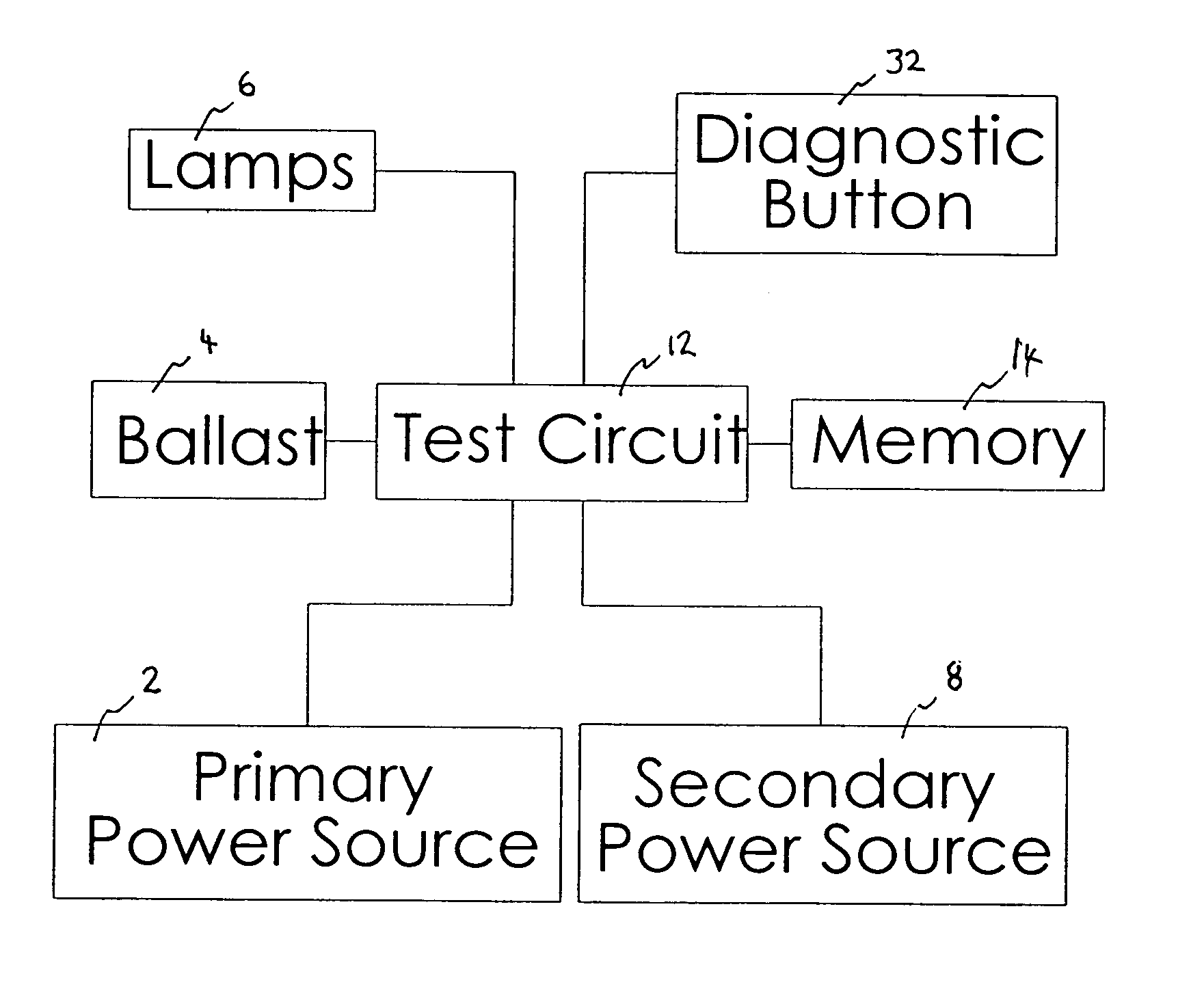
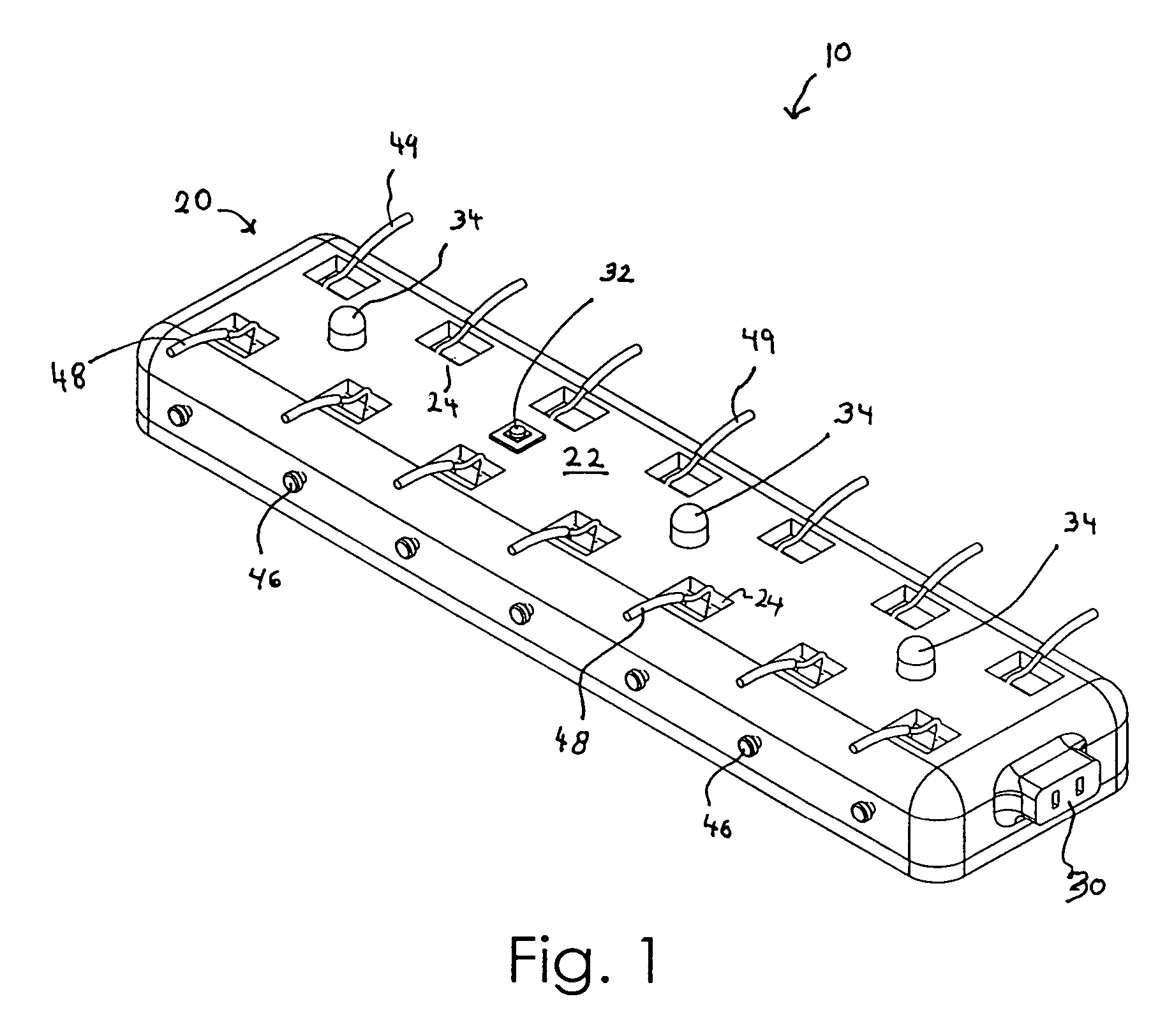
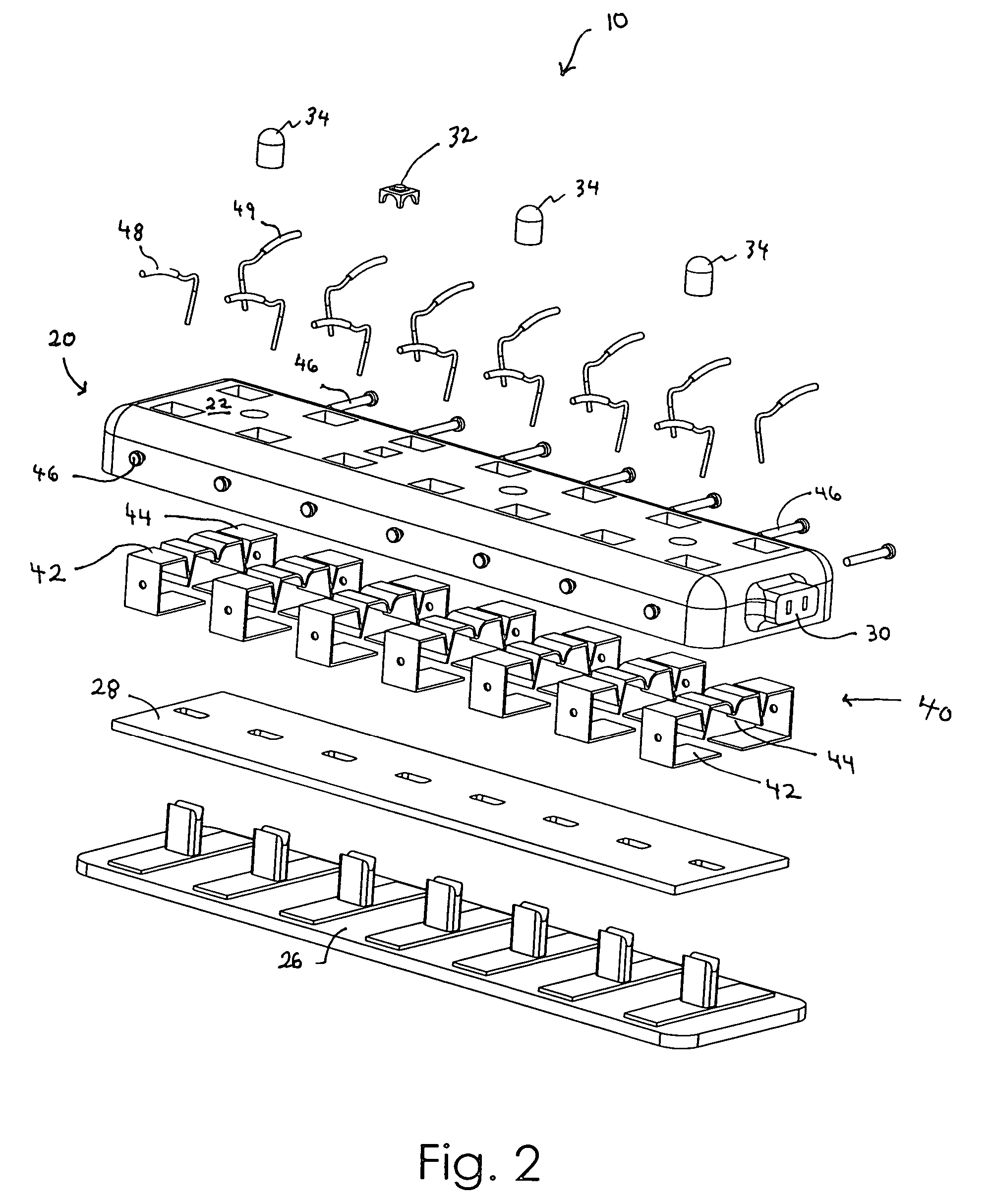
[0021]An apparatus 10 for testing and monitoring a fluorescent lamp assembly according to one embodiment of the invention is shown in FIG. 1. While this apparatus 10 will be described in detail below, it should first be appreciated how the present invention may be utilized along with a conventional fluorescent lamp assembly having a ballast 4 and at least one fluorescent lamps 6 (FIG. 6). FIG. 6 is a block diagram illustrating schematically how the present apparatus 10 includes a test circuit 12 that may be electrically connected to a primary power source 2 such as A / C electrical power, to a lamp system ballast 4, and to at least one fluorescent lamps 6. The test circuit 12 may be connected thereto with quick connect components as will be described in more detail later. The test circuit 12 may be in the form of a p...


PUM


Abstract

A monitoring and testing apparatus for quick-connection to a fluorescent lamp assembly includes a test circuit positioned in a casing and having wire receiving clips for quick receipt and release of wires from a ballast and lamp, whereby to electrically connect the ballast and lamp. The test circuit obtains voltage data from the ballast and lamp for evaluation indicative of operability. If either voltage data is out of a predictable range, an appropriate fault is stored in memory. When a diagnostic button is depressed by a user, the test circuit evaluates the state of the memory and energizes an appropriate LED to indicate if the ballast or lamp is inoperable. The quick-connect assembly enables a novice to correctly and quickly connect a ballast or lamps to the test apparatus and to diagnose an inoperable lamp assembly.

Description

BACKGROUND OF THE INVENTION[0001]This invention relates generally to fluorescent lamp system ballasts and, more particularly, to a method and quick-connect apparatus for testing and monitoring a fluorescent lamp assembly ballast and lamps.[0002]Fluorescent lights are more complex than incandescent lights. Main line electrical power can not be provided directly to a fluorescent light but must first be regulated by a ballast. Complex wiring systems of ballasts and fluorescent lighting systems has made their installation and maintenance a job for professional electricians rather than for ordinary maintenance personnel or the do-it-yourselfer.[0003]The complexities of fluorescent light assemblies with a ballast make it difficult even for an electrician to determine whether an inoperable system is due to the ballast, a lamp, or an overall lack of electrical power. In the past, troubleshooting an inoperable system was often accomplished by trial and error, i.e. by replacing a bulb or ball...

Claims


Application Information

Patent Timeline
Patent Type & Authority Patents(United States)
IPC IPC(8): G01R31/24H05B37/03
CPCG01R31/245H05B37/03H05B47/20
Inventor SCHRIEFER, JAY R.
Owner SCHRIEFER JAY R
Why Eureka
Try Eureka