
Arc fault circuit detector having two arc fault detection levels

a technology of arc fault circuit and detector, which is applied in the direction of emergency protective arrangement details, emergency protective arrangement for limiting excess voltage/current, electrical equipment, etc., can solve the problems of low power arc between the two conductors and arc faul

Inactive Publication Date: 2005-12-06
PASS SEYMOUR
View PDF12 Cites 38 Cited by
  • Summary
  • Abstract
  • Description
  • Claims
  • Application Information

AI Technical Summary

Benefits of technology

"The present invention is an arc fault protective device that includes a sensor, a level detection circuit, an arc detection circuit, and a response mechanism. The sensor generates a sensor signal in response to an electrical current signal in an electrical distribution system. The level detection circuit compares the magnitude of the electrical current signal to predetermined threshold levels and generates a first level detection signal if the magnitude is between the first and second threshold levels. The arc detection circuit compares the sensor signal to arc fault signatures and generates an arc detection signal if the sensor signal corresponds to the first or second arc fault signature. The response mechanism is responsive to the detected arc fault and can disconnect a load from the electrical distribution system. The invention provides an effective and reliable protection against arc faults in electrical distribution systems."

Problems solved by technology

An arc fault may be caused by damaged insulation on the hot line conductor or neutral line conductor, or on both the hot line conductor and the neutral line conductor.
The damaged insulation may cause a low power arc between the two conductors and a fire may result.
This type of fault may also be occasioned by a loose terminal in a branch circuit of a distribution network.

Method used


Image

  • Arc fault circuit detector having two arc fault detection levels
  • Arc fault circuit detector having two arc fault detection levels

Examples


Embodiment Construction

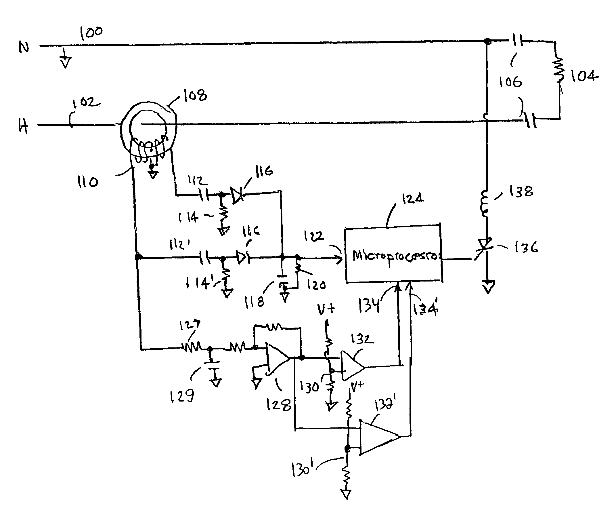
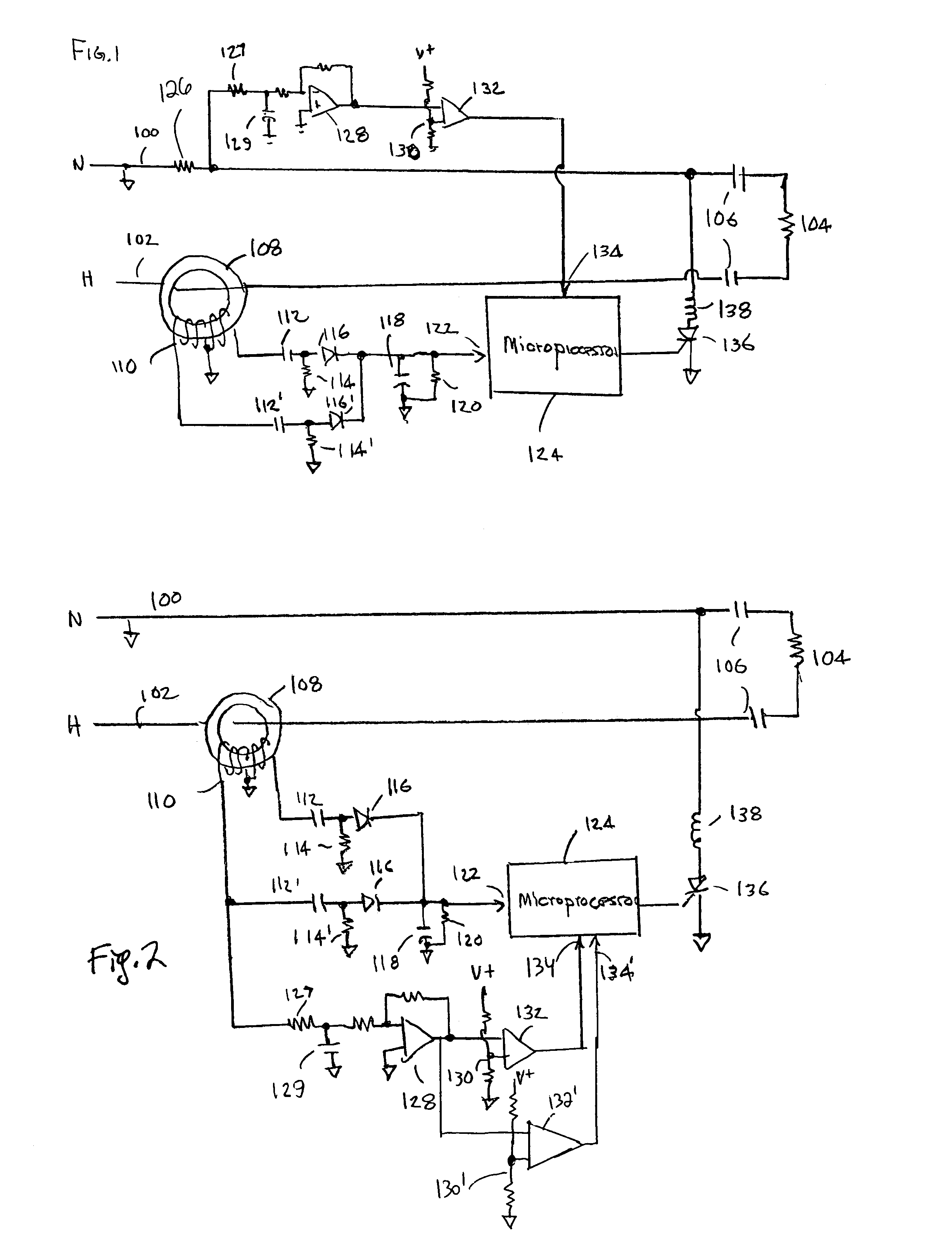
[0019]Reference will now be made in detail to the present exemplary embodiments of the invention, examples of which are illustrated in the accompanying drawings. Wherever possible, the same reference numbers will be used throughout the drawings to refer to the same or like parts. An exemplary embodiment of the AFCI of the present invention is shown in FIG. 1, and is designated generally throughout by reference numeral 10.

[0020]Arc faults are detected on the basis of monitoring the current of the protected branch circuit. The present invention is configured to distinguish routine electrical noise current from current irregularities that represent a true arc fault condition. Examples of routine electrical noise current include noise current caused by arcs generated by motor brushes or the toggling of wall switches. While the signal to noise ratio is poorer for low current A-type series arc faults as compared to high current parallel B-type arcs, a longer period is allowed for the AFCI...


PUM


Abstract

The present invention is directed to an arc fault protective device that includes a sensor configured to generate a sensor signal in response to an electrical current signal propagating in an electrical distribution system. A level detection circuit is coupled to the electrical distribution system. The level detection circuit is configured to generate a first level detection signal if a magnitude of the electrical current signal is between a first predetermined threshold level and a second predetermined threshold level. The level detection circuit also is configured to generate a second level detection signal if a magnitude of the electrical current signal is greater than the second predetermined threshold level. An arc detection circuit is coupled to the sensor and the level detection circuit. The arc detection circuit is configured to compare the sensor signal to a first arc fault signature and a second arc fault signature. The arc detection circuit is configured to provide an arc detection signal in response to the first level detection signal if the sensor signal corresponds to the first arc fault signature. The arc detection circuit also is configured to provide an arc detection signal in response to the second level detection signal if the sensor signal corresponds to the second arc fault signature. A response mechanism is coupled to the arc detection circuit, the response mechanism being responsive to the arc detection signal.

Description

[0001]CROSS-REFERENCE TO RELATED APPLICATIONS[0002]This is a continuation-in-part of U.S. patent application Ser. No. 09 / 788,206, now U.S. Pat. No. 6,839,208, filed on Feb. 16, 2001 and U.S. patent application Ser. No. 09 / 990,809, now U.S. Pat. No. 6,798,628, filed on Nov. 16, 2001, the contents of which are relied upon and incorporated herein by reference in their entirety, and the benefit of priority under 35 U.S.C. §120 is hereby claimed. U.S. patent application Ser. No. 09 / 788,206 claims the benefit of priority to U.S. Provisional Application Ser. No. 60 / 183,287 filed on Feb. 17, 2000 and U.S. patent application Ser. No. 09 / 990,809 claims the benefit of priority U.S. Provisional Application Ser. No. 60 / 249,480 filed on Nov. 17, 2000, the contents of which are also relied upon and incorporated herein by reference in their entirety, and the benefit of priority under 35 U.S.C. §119(e) is hereby claimed.BACKGROUND OF THE INVENTION[0003]1. Field of the Invention[0004]The present inve...

Claims


Application Information

Patent Timeline
Patent Type & Authority Patents(United States)
IPC IPC(8): H02H1/00H02H3/00
CPCH02H1/0015
Inventor MACBETH, BRUCE F.RICHARDS, JEFFREY C.
Owner PASS SEYMOUR
Learn More