Fixing and protecting arrangement for a capacitor

a technology for fixing and protecting arrangements, which is applied to variable capacitors, multi-fixed capacitors, electrical devices, etc., can solve problems such as time-consuming fixing techniques, prior art does not give capacitors particular protection against heating, and problems such as problems such as problems such as affecting the effect of heat dissipation

Active Publication Date: 2005-12-06
VACON OY
View PDF7 Cites 2 Cited by
  • Summary
  • Abstract
  • Description
  • Claims
  • Application Information

AI Technical Summary

Benefits of technology

[0005]An object of the present invention is to eliminate drawbacks of the prior art and to provide a new kind of solution for fixing a capacitor to an electrotechnical device, which solution further offers the capacitor effective protection against heating.
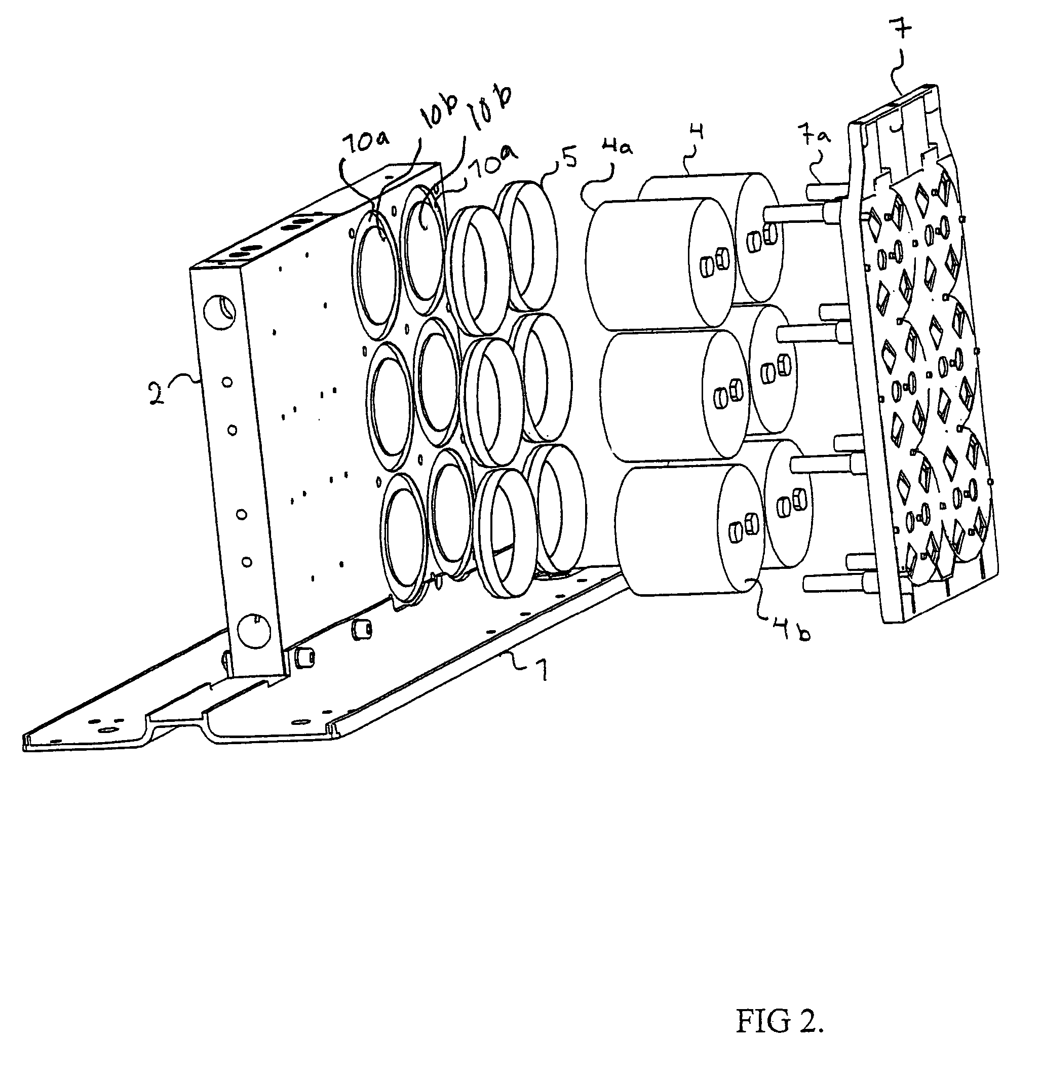
[0012]Further, the capacitor may be fixed to the cooling element with an adapter collar that is positioned between the capacitor and the cooling element. Such an adapter collar can be manufactured simply and inexpensively, for instance by extruding it from a plastic appropriate for the purpose.
[0015]By using an adapter collar and an insulating film, the drift distance between the capacitor and the cooling element can be made sufficiently long. The drift distance may be further increased by reducing the inner periphery diameter of the lower portion of the adapter collar, whereby the length of the drift distance relative to the lower surface of the capacitor and the cooling element increases. The adapter collar is arranged to form a tight and clean contact between the lower surface of the capacitor and the cooling element in such a way that the drift distance is not affected by detrimental dust or moisture. A tight adapter collar also prevents heat-conductive paste from drying if such is used for conducting heat.
[0017]The diameter of the recess portion arranged in the cooling element is preferably dimensioned in such a way that the capacitor becomes tightly positioned against the surface of the cooling element when fitted to the adapter collar. Significant advantages are achieved with this tight arrangement in the mounting and cooling of the capacitor, because the capacitor needs not be unduly pressed against the cooling element, and a tight contact is provided between the capacitor bottom and the cooling element, whereby no heat-insulating air gap remains between them, but the heat can be efficiently transferred to the cooling element.
[0018]Using a fixing and protecting arrangement according to the invention allows the working steps of the capacitor mounting to be reduced, which results in quicker and less expensive mounting of higher quality as well as in an end product, such as a frequency converter, of higher quality.

Problems solved by technology

Such fixing solutions according to the prior art are, however, problematic, because there must always be a fixing means of a precisely suitable size available, and for screw-mounting, there must be a screw fixed or fixable to a capacitor.
Further, such fixing is time-consuming with respect to the fixing technique.
Further still, the fixing solutions according to the prior art do not give the capacitor any particular protection against heating.

Method used


Image

  • Fixing and protecting arrangement for a capacitor
  • Fixing and protecting arrangement for a capacitor
  • Fixing and protecting arrangement for a capacitor

Examples


Embodiment Construction

[0025]Referring to FIGS. 1 to 5, an example of the structure and operation of a typical fixing and protecting arrangement for a capacitor is explained.

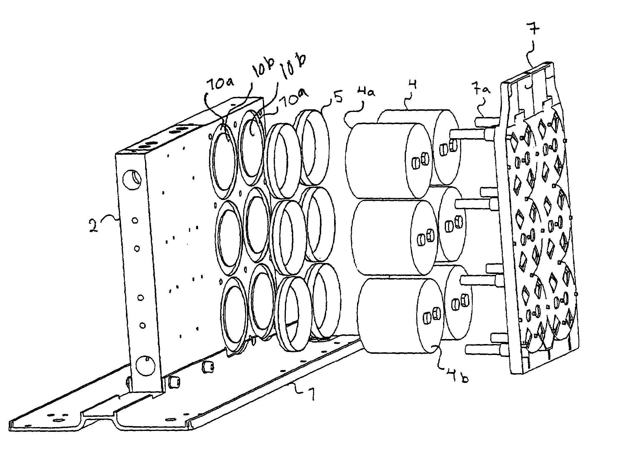
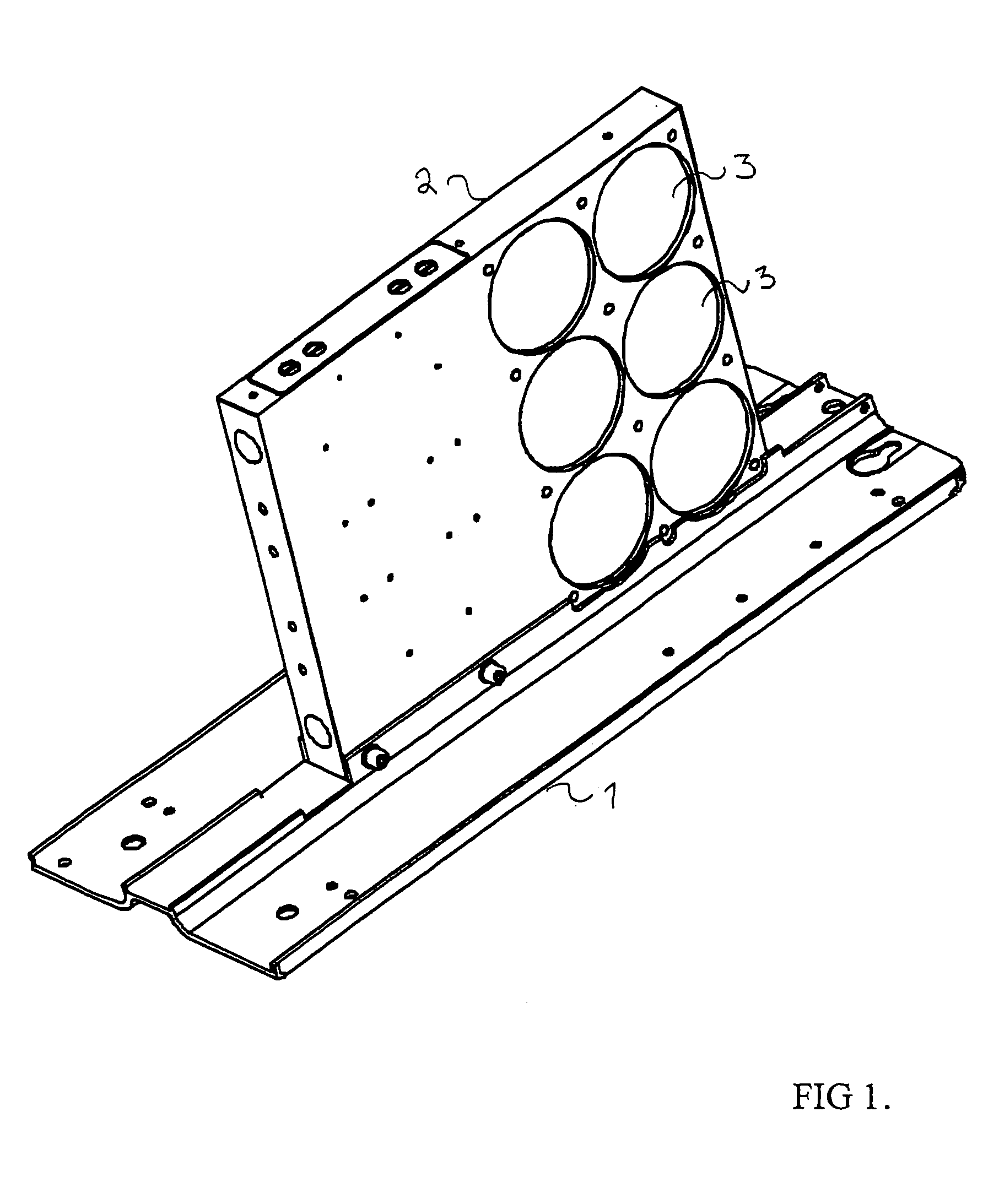
[0026]In accordance with FIGS. 1 and 2, the fixing and protecting arrangement for a capacitor comprises a support base 1. The support base 1 is provided with a cooling element 2, which functions in this embodiment also as the frame of the whole device. Thus, the cooling element 2 enables a firm fixing base for capacitors of the type shown in FIG. 2.

[0027]The cooling element 2 is, in accordance with FIG. 1 or 2, provided with recesses 3, 10a and 10b for fixing capacitors 4, there being one or more recesses, depending on the number of capacitors 4. The capacitors 4 are intended to be fixed into the recesses 3, 10a and 10b.

[0028]FIG. 1 shows an embodiment of a fixing and protecting arrangement for a capacitor. In this embodiment, the structure of the recess 3 is cylinder-like and the receiving surface of the recess 3 and the lower surfa...


PUM


Abstract

The present invention relates to a fixing and protecting arrangement for a capacitor. The arrangement comprises a cooling element, one or more recesses arranged in the cooling element, and a capacitor intended to be fixed into each recess. The arrangement is characterized in that it comprises one or more recesses arranged in the cooling element, in which recess the capacitor is intended to be arranged in such a way that the lower surface of the capacitor is in contact with the cooling element for transferring heat from the capacitor to the cooling element.

Description

FIELD OF THE INVENTION[0001]The invention relates to a fixing and protecting arrangement for a capacitor.BACKGROUND OF THE INVENTION[0002]A fixing and protecting arrangement according to the invention can be used in an electrotechnical device, for example for fixing capacitors positioned in a frequency converter to fixing parts of the device and for protecting them against heating.[0003]It is known from the prior art to fix the capacitors of a device to a fixing plate by using different fixing means, such as clips, bands or screws. One known way of fixing comprises a bolt fixed to a capacitor, which bolt is usually at the opposite end to its terminals end and by which bolt the capacitor is fixed to the fixing plate below it with a nut.[0004]Such fixing solutions according to the prior art are, however, problematic, because there must always be a fixing means of a precisely suitable size available, and for screw-mounting, there must be a screw fixed or fixable to a capacitor. Further...

Claims


Application Information

Patent Timeline
Patent Type & Authority Patents(United States)
IPC IPC(8): H01G2/08H01G4/38
CPCH01G2/08H01G4/38
Inventor MIETTINEN, OSMONORRENA, JUHAKOSKINEN, TIMOPALOMAKI, LEO
Owner VACON OY
Why Eureka
Try Eureka