Dynamic range compression

a compression and dynamic range technology, applied in the field of dynamic range compression (drc) of imagery, can solve the problems of difficult or impossible detection of details corresponding to objects on the ground

Inactive Publication Date: 2005-12-06
LOCKHEED MARTIN CORP
View PDF44 Cites 29 Cited by
  • Summary
  • Abstract
  • Description
  • Claims
  • Application Information

AI Technical Summary

Problems solved by technology

Accordingly, details corresponding to objects on the ground can be difficult or impossible to detect if the low-frequency background gradient is not removed.

Method used


Image

  • Dynamic range compression
  • Dynamic range compression
  • Dynamic range compression

Examples


Embodiment Construction

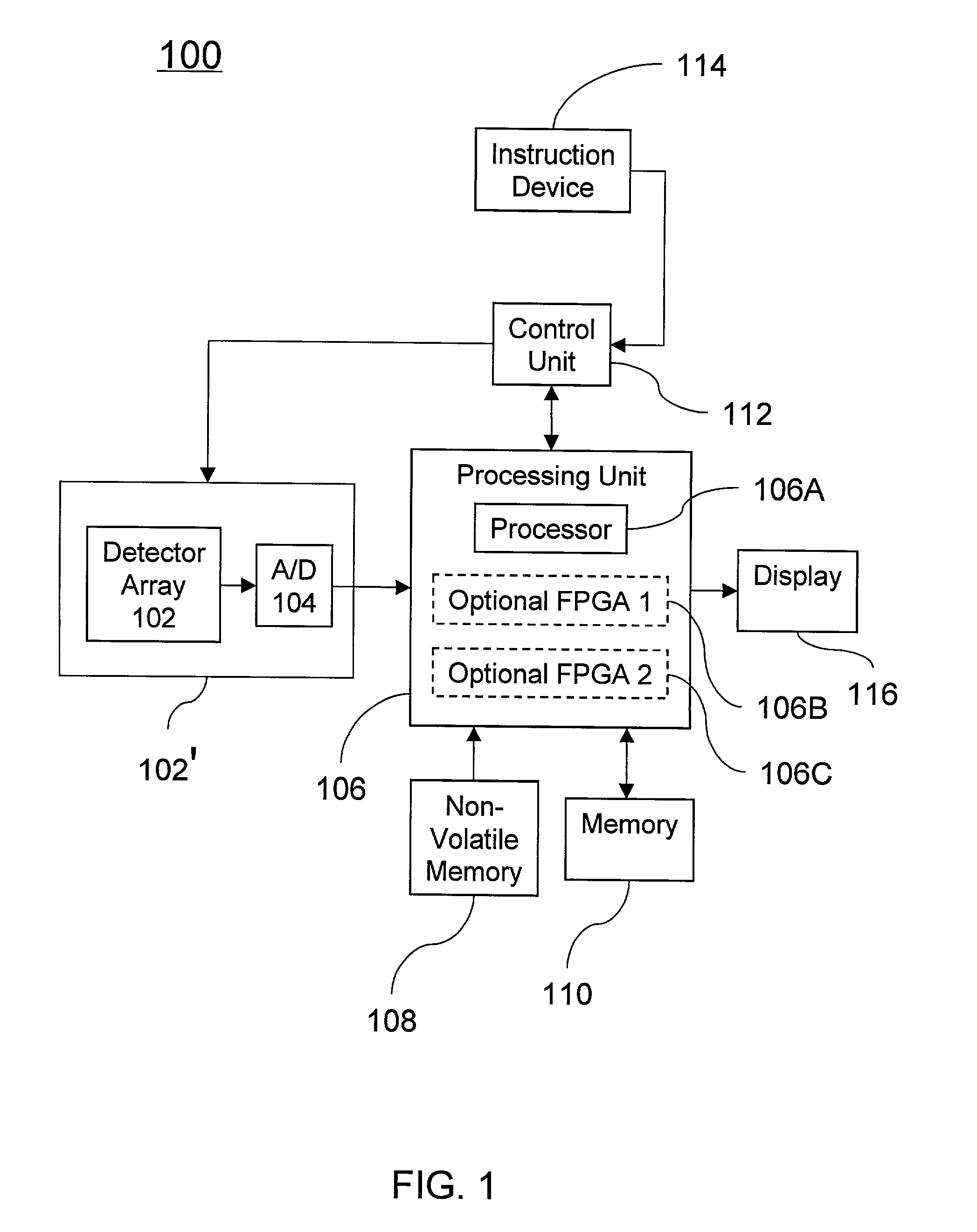
[0028]Various aspects of the invention will now be described in connection with a number of exemplary embodiments. To facilitate an understanding of the invention, many aspects of the invention are described in terms of actions to be performed by a processor unit, a processor, and / or one or more field programmable gate array (FPGA) devices. It will be recognized that in each of the embodiments, the various actions could be performed by elements of a computer system. Further, it will be recognized that in each of the embodiments, the various actions could be performed by specialized circuits (e.g., discrete logic gates interconnected to perform a specialized function), by program instructions being executed by one or more processors, or by a combination of both. Moreover, the invention can additionally be considered to be embodied entirely within any form of computer readable carrier such as solid-state memory, magnetic disk, optical disk or modulated carrier wave (such as radio freq...


PUM


Abstract

A method and apparatus for processing image data is described, comprising acquiring a frame of image data and compressing the dynamic range of the frame of image data using a dynamic range compression (DRC) algorithm that utilizes down-sampling, median filtering, and up-sampling. The DRC algorithm comprises down-sampling a frame of image data comprising a first array of pixels to generate a second array of pixels, applying a first median filter to the second array of pixels to generate a blurred array of pixels, up-sampling the blurred array of pixels, and removing at least a portion of low-frequency gradient data generated by previous steps from the frame of image data.

Description

CROSS REFERENCE TO RELATED APPLICATIONS[0001]The present application is related to U.S. Patent Application “Extended Range Image Processing For Electro-Optical Systems”, Ser. No. 09 / 841,079 and to U.S. Patent Application entitled “Scene-Based Non-Uniformity Correction For Detector Arrays”, Ser. No. 09 / 840,920 both filed even date herewith, the contents of which are hereby incorporated herein by reference in their entirety.BACKGROUND[0002]1. Field of the Invention[0003]The present invention relates to dynamic range compression (DRC) of imagery. An exemplary aspect of the present invention relates to DRC of infrared (IR) imagery and, in particular, to real-time DRC of IR imagery collected with a forward looking infrared (FLIR) camera system.[0004]2. Background Information[0005]Imagery collected with a large field of view imaging apparatus, such as a wide field of view (WFOV) forward looking infrared (FLIR) pilotage system, may contain low-frequency gradient data, such as ground-to-sky...

Claims


Application Information

Patent Timeline
Patent Type & Authority Patents(United States)
IPC IPC(8): G06T5/20G06T5/40H04N5/208H04N5/217H04N5/33H04N5/365H04N5/367
CPCG06T5/20H04N5/2176H04N5/33G06T2207/20032G06T2207/20208H04N5/3656H04N5/367H04N25/63H04N25/674H04N25/68
Inventor ALDERSON, TIMOTHYTENER, GENE D.HOPKINS, VALETE C.STUART, CHARLIE W.NGUYEN, CHINH X.
Owner LOCKHEED MARTIN CORP
Why Eureka
Try Eureka