Cable

a technology of identifying information and cables, applied in the field of cables, can solve the problems of reducing the efficiency of cable operations, difficult to apply all cable identifying information, and inability to decipher cable identifying information

Active Publication Date: 2005-12-06
THE FUJIKURA CABLE WORKS LTD
View PDF7 Cites 160 Cited by
  • Summary
  • Abstract
  • Description
  • Claims
  • Application Information

AI Technical Summary

Benefits of technology

[0009]In order to solve the above-mentioned problems affecting conventional technology, it is an object of this invention to provide a cable to and from which a large volume of cable identifying information can be simply and speedily written-in and read-out.

Problems solved by technology

Accordingly, it is not easy to apply all of the cable identifying information of a cable simply by printing or marking that information on the surface of a sheath or by applying QR code to the surface of a sheath.
Also, such factors make it difficult to identify a particular cable amongst a plurality of cables, which results in a decrease of efficiency in operations performed on the cable.
Moreover, cable identifying information that is printed or marked onto the outside surface of a cable is exposed, so that after a period of time has elapsed since a cable was installed, it may become impossible to decipher the cable identifying information due to wear or the like, making it impossible to identify the cable.
Even when QR code printing paper is adhered to the external surface of the sheath of a cable using a protective film, the protective film may peel off from the sheath, resulting in exactly the same problem.

Method used


Image

  • Cable
  • Cable
  • Cable

Examples


first embodiment

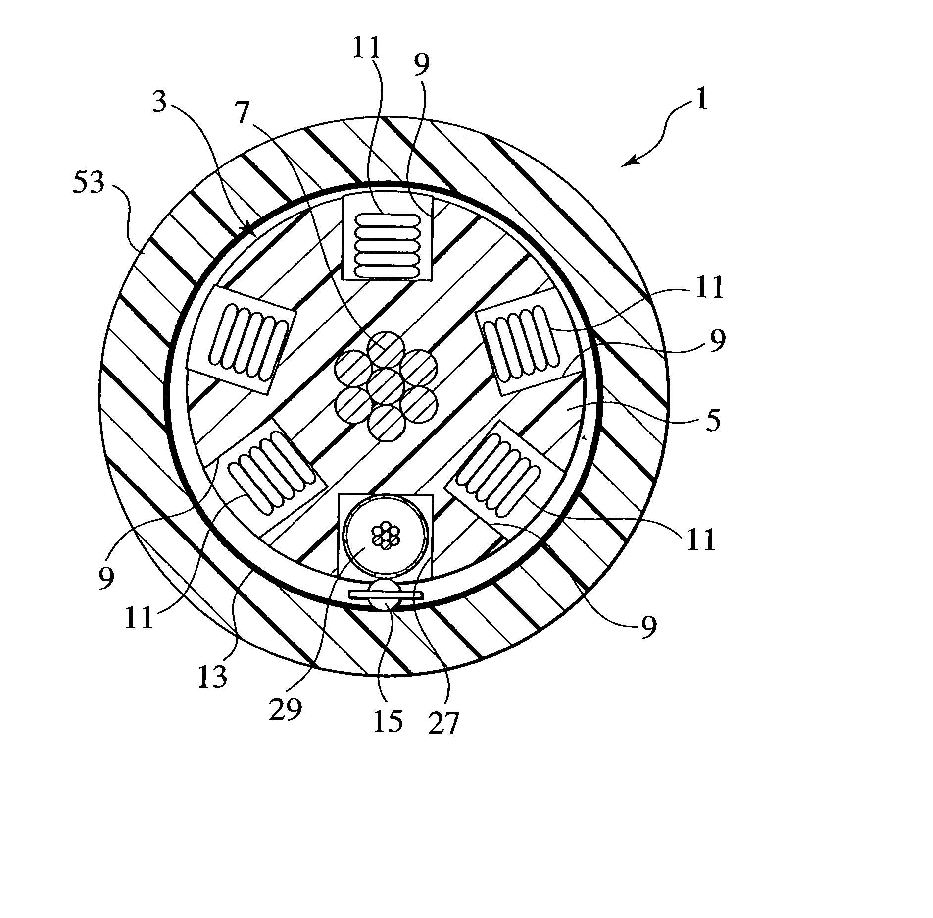
[0034]FIG. 1 is a cross-sectional view of an optical fiber cable according to this invention.

[0035]As shown in FIG. 1, a cable core 3 forms the major component of an optical fiber cable 1 according to a first embodiment of this invention. More specifically, this cable core 3 includes a slotted core 5 in the center part of which is provided a strength member 7 formed of stranded steel wire. Further, a plurality (according to this embodiment, five) of slots 9 are formed in helical formation around the outside of the slotted core 5. A plurality (according to this embodiment, five) of optical fiber ribbons 11 are accommodated in each of slots 9. Further, a cable core wrap 13 is applied to the outside of the slotted core 5, accommodating the optical fiber ribbons remained inside the slots 9.

[0036]An integrated member with a chain of Radio Frequency Identification elements (“RFIDs”) 15 for identifying the optical fiber cable 1 is disposed in the cable core 3. This integrated member with a...

second embodiment

[0059]As shown in FIG. 7 a cable core 57 forms the major component of an optical fiber cable 55 according to this invention. More specifically, this cable core 57 includes a central strength member 61 at the center of the cable core, consisting of seven stranded steel wires, covered with the central strength member sheath 59. Further, a plurality (12 according to this embodiment) of simplex optical cables 63 are collectively, tightly stranded around the outside of the strength member sheath 59. A wrap 65 is disposed around the outside of the plurality of simplex optical cables 63 and a transmission coaxial cable 64 for preventing the simplex optical cables 63 and the transmission coaxial cable 64 from loosening from the strength member sheath 59.

[0060]An integrated member with a chain of RFIDs 67 is disposed in the cable core 57. A detailed explanation of this integrated member with a chain of RFIDs 67 used for identifying the optical fiber cable 55 is omitted here as the structure ...

third embodiment

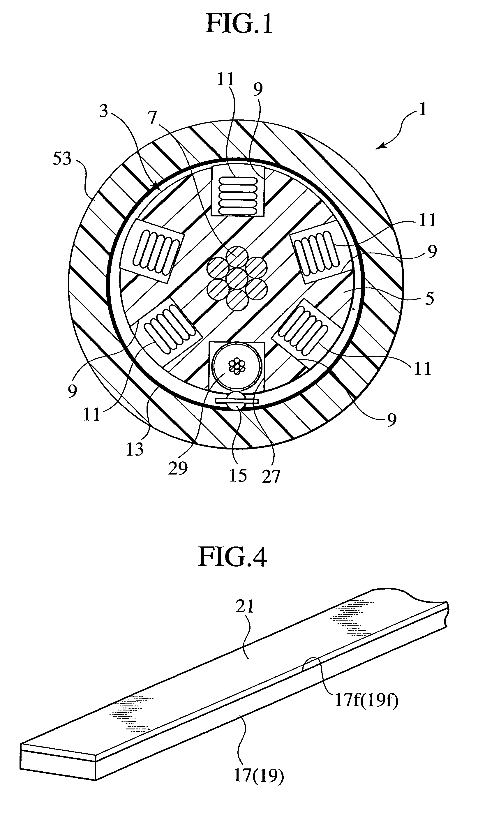
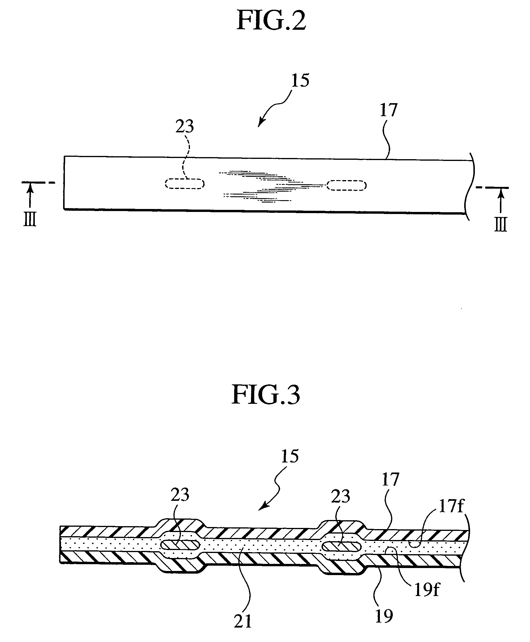
[0064]FIG. 8 is a cross-sectional view of an optical fiber cable according to a third exemplary embodiment of this invention. FIG. 9 is a plan view of an integrated member with a chain of RFIDs of this invention and FIG. 10 is a cross-sectional view taken along the line X—X of FIG. 9.

[0065]As shown in FIG. 8, a cable core 103 forms the major component of an optical fiber cable 101 according to a third embodiment of this invention. More specifically, this cable core 103 includes a slotted core 105 at the center of which is provided a central strength member 107 consisting of seven stranded steel wires. Further, a plurality (five, according to this embodiment) of slots 109 are formed in a helical formation around the outside of the slotted core 105. A plurality (five, according to this embodiment) of optical fiber ribbons 111 are layered and accommodated in each of the slots 109. Further, a wrap 113 is disposed around the outside of the slotted core 5, accommodating the optical fiber ...


PUM

PropertyMeasurementUnit
diameteraaaaaaaaaa
diameteraaaaaaaaaa
distanceaaaaaaaaaa

Abstract

A cable wherein even when there is a substantial volume of cable identifying information for identifying the cable, all of that cable identifying information can be simply and speedily written-in. This cable has a cable core, an integrated member with a chain of RFIDs including a plurality of RFID elements arranged at suitable intervals along a longitudinal direction of the cable core, to and from which cable identifying information can be written-in and read-out by transmission of electromagnetic energy, and a transmission coaxial cable for collectively writing-in cable identifying information to all of the RFID elements.

Description

CROSS REFERENCE TO RELATED APPLICATIONS[0001]This application claims benefit of priority to Japanese Patent Application No. 2003-35037 and Japanese Patent Application No. 2003-35048 both filed on Feb. 13th, 2003 in the Japanese Patent Office, the entire contents of which are herein incorporated by reference.BACKGROUND OF THE INVENTION[0002]1. Field of the Invention[0003]This invention relates to a cable, such as an optical fiber cable, metal cable or the like, providing functionality enabling ready identification of the cable, and an integrated member with a chain of RFIDs (Radio Frequency Identification) used for identifying the cable.[0004]2. Description of Relevant Art[0005]Usually, information identifying a cable that enables one cable to be identified from others is associated with the cable sheath (either directly or indirectly). This information enables the particular cable to be identified amongst a plurality of cables laid in, for example, a multi-way conduit or duct when p...

Claims


Application Information

Patent Timeline
Patent Type & Authority Patents(United States)
IPC IPC(8): G02B6/44H01B7/36
CPCG02B6/447H01B7/368G02B6/562
Inventor KOYASU, OSAMUKOBAYASHI, KAZUNAGASHIOBARA, SATORUOSATO, KENHARA, MASASHITANAKA, SHIMEIHONJO, TAKESHIOHASHI, KEIJI
Owner THE FUJIKURA CABLE WORKS LTD
Why Eureka
Try Eureka