High print rate merging and finishing system for parallel printing

a technology of parallel printing and merging system, applied in the field of image production, can solve the problems of multiple marking engines, multiple finishing systems, and dedicated media paths between them, and achieve the effect of merging the output of multiple marking engines and reducing the number of finishing systems

Inactive Publication Date: 2005-12-06
XEROX CORP
View PDF19 Cites 121 Cited by
  • Summary
  • Abstract
  • Description
  • Claims
  • Application Information

AI Technical Summary

Problems solved by technology

One disadvantage of existing cluster systems is that the output is not merged, meaning that an operator may have to gather the output of a distributed job from multiple exit trays.
Another disadvantage is that redundant finishers may be required.
One disadvantage of presently available systems is that once configured, the feeding, marking, finishing systems, and the media paths between them are dedicated and not easily changeable.
Another problem arises from merging the output of multiple marking engines.
The act of accelerating sheets to a different velocity may require a significant media path length, especially for accommodating large size media.
There are practical limits to the speed of the high velocity media path.
In addition, the speed of the high velocity media path may be further limited by the capacity of the finishing equipment.

Method used


Image

  • High print rate merging and finishing system for parallel printing
  • High print rate merging and finishing system for parallel printing
  • High print rate merging and finishing system for parallel printing

Examples


Embodiment Construction

)

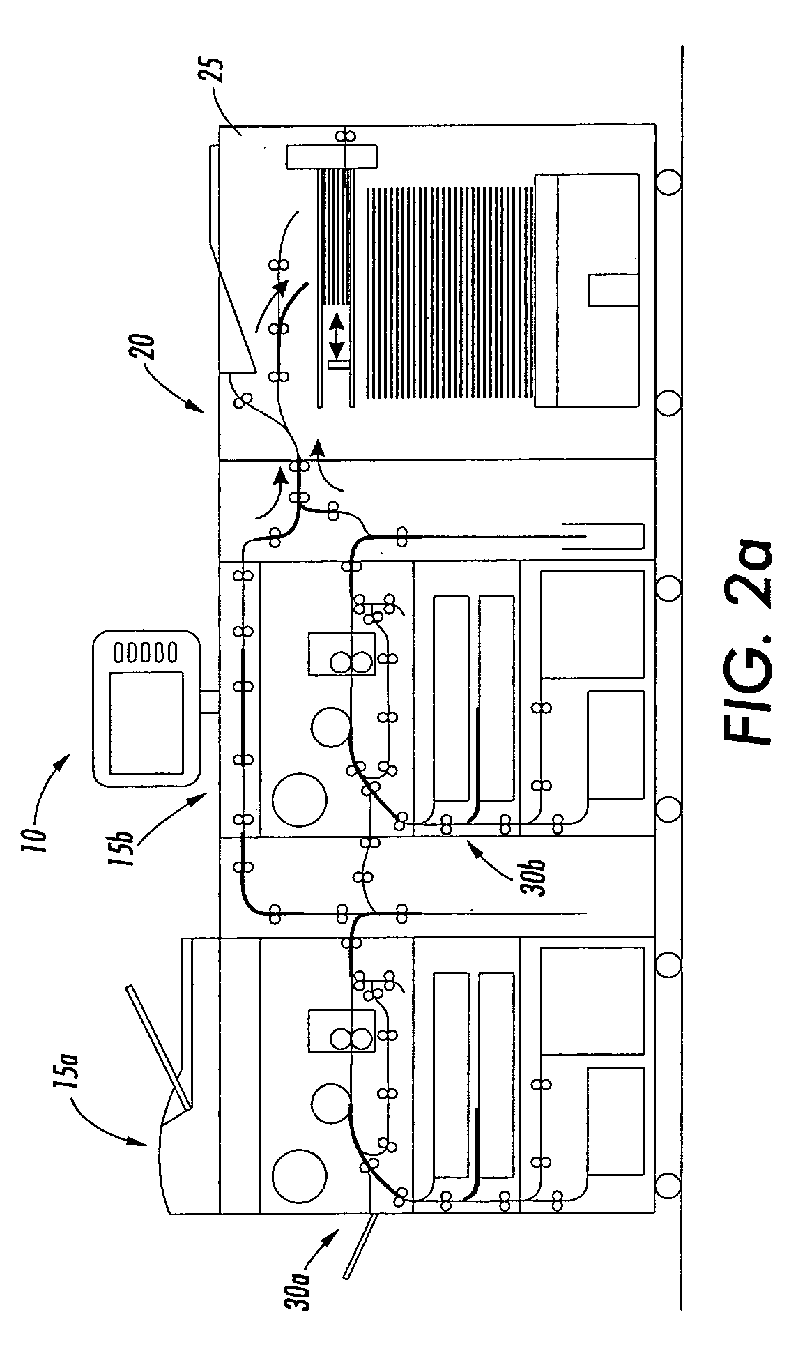
[0019]FIGS. 2a and 2b illustrate systems incorporating features of the disclosed embodiments. Although the disclosed embodiments will be described with reference to the embodiment shown in the drawings, it should be understood that the disclosed embodiments can be embodied in many alternate forms of embodiments. In addition, any suitable size, shape or type of elements or materials could be used.

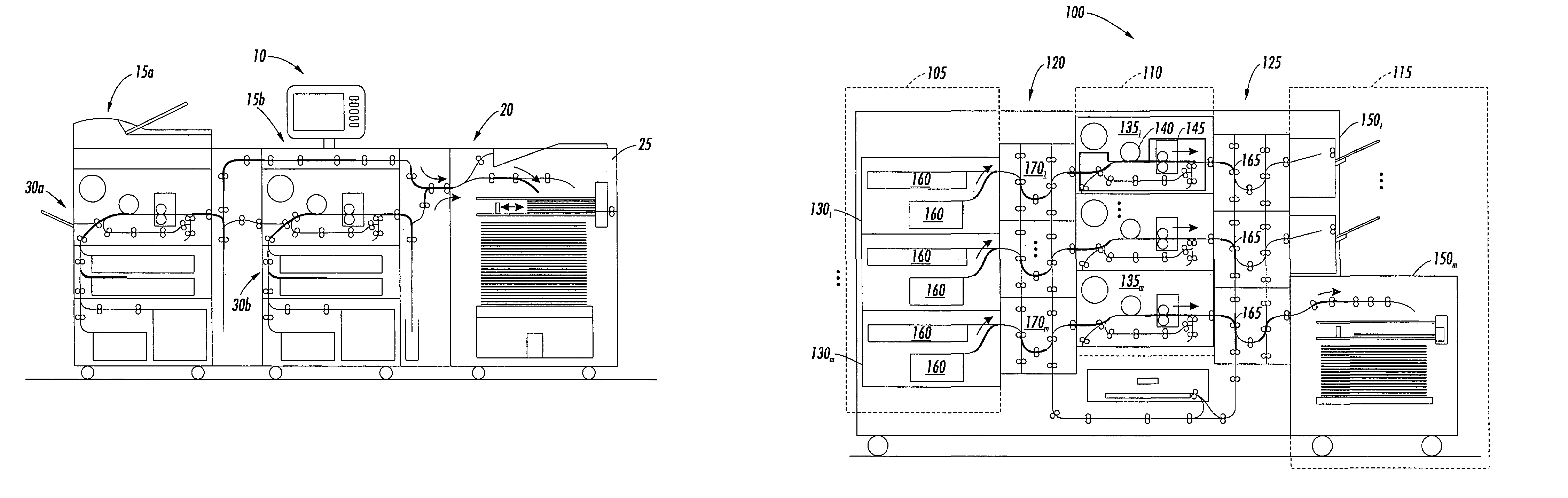
[0020]As shown in FIG. 2a, a system 10 is generally a printing system that includes at least two marking systems 15a, 15b and a finishing system 20. A media path is provided such that the sheets printed by the two marking systems 15a, 15b can be merged, one on top of the other, at some point before delivery to the compiling station 25 of the finishing system 20. It should be appreciated that this merging function could take place in the media path upstream of the finisher, as shown in FIG. 2a, or in the media path of the finishing system. In the embodiment shown in FIG. 2a, the two marking ...


PUM


Abstract

A system for printing media includes a plurality of marking engines for outputting printed media in a stream, a media path system operable to transport the printed media from the marking engines to one or more finishing stations such that the streams are merged and transported one on top of the other and one or more finishing stations capable of compiling media in groups of 2 or more sheets for post processing the printed media into one or more completed jobs.

Description

BACKGROUND[0001]1. Field[0002]The disclosed embodiments relate to image production and, more particularly, to a system and method for printing and finishing media.[0003]2. Brief Description of Related Developments[0004]Incorporated by reference, where appropriate, by way of background, are the following references variously relating to what have been variously called “tandem engine” printers, “cluster printing”, “output merger” etc., for example, Xerox Corp. U.S. Pat. No. 5,568,246 issued Oct. 22, 1996; Canon Corp. U.S. Pat. No. 4,587,532; Xerox Corp. U.S. Pat. No. 5,570,172 to Acquaviva; T / R Systems Barry et al U.S. Pat. No. 5,596,416; Xerox Corp. U.S. Pat. No. 5,995,721 to Rourke et al; Canon Corp. Fujimoto U.S. Pat. No. 4,579,446; Xerox Corp. Provisional Application No. 60 / 478,749 filed Jun. 16, 2003 by Robert J. Lofthus, et al, entitled “UNIVERSAL FLEXIBLE PLURAL PRINTER TO PLURAL FINISHER SHEET INTEGRATION SYSTEM; a 1991 “Xerox Disclosure Journal” publication of November–Decemb...

Claims


Application Information

Patent Timeline
Patent Type & Authority Patents(United States)
IPC IPC(8): G03G15/00B41J29/38
CPCG03G15/65G03G2215/00021
Inventor MANDEL, BARRY P.LOFTHUS, ROBERT M.MOORE, STEVEN R.KRUCINSKI, MARTINQUESNEL, LISBETH S.
Owner XEROX CORP
Why Eureka
Try Eureka