
Enclosure for a light source

a light source and enclosure technology, applied in the field of illumination, can solve the problem that the source is an obstacle to those moving near the wall

Active Publication Date: 2005-12-20
HELENOWSKI JACEK
View PDF22 Cites 30 Cited by
  • Summary
  • Abstract
  • Description
  • Claims
  • Application Information

AI Technical Summary

Benefits of technology

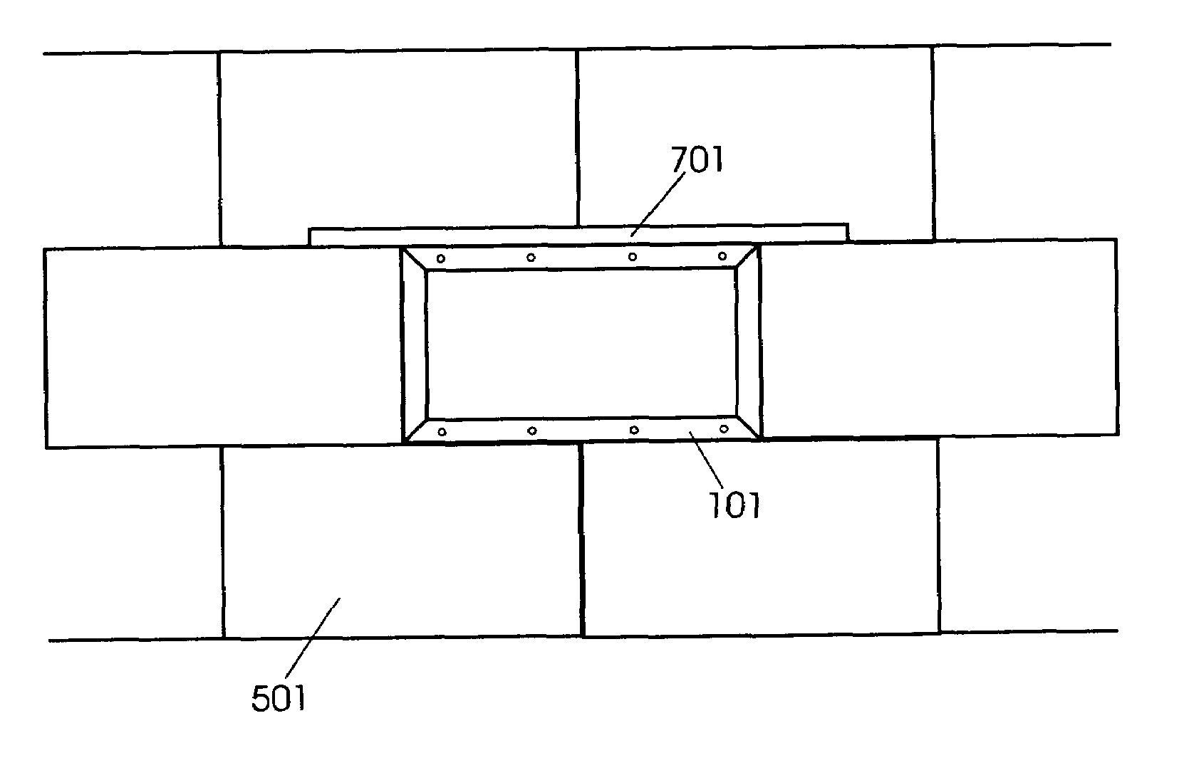
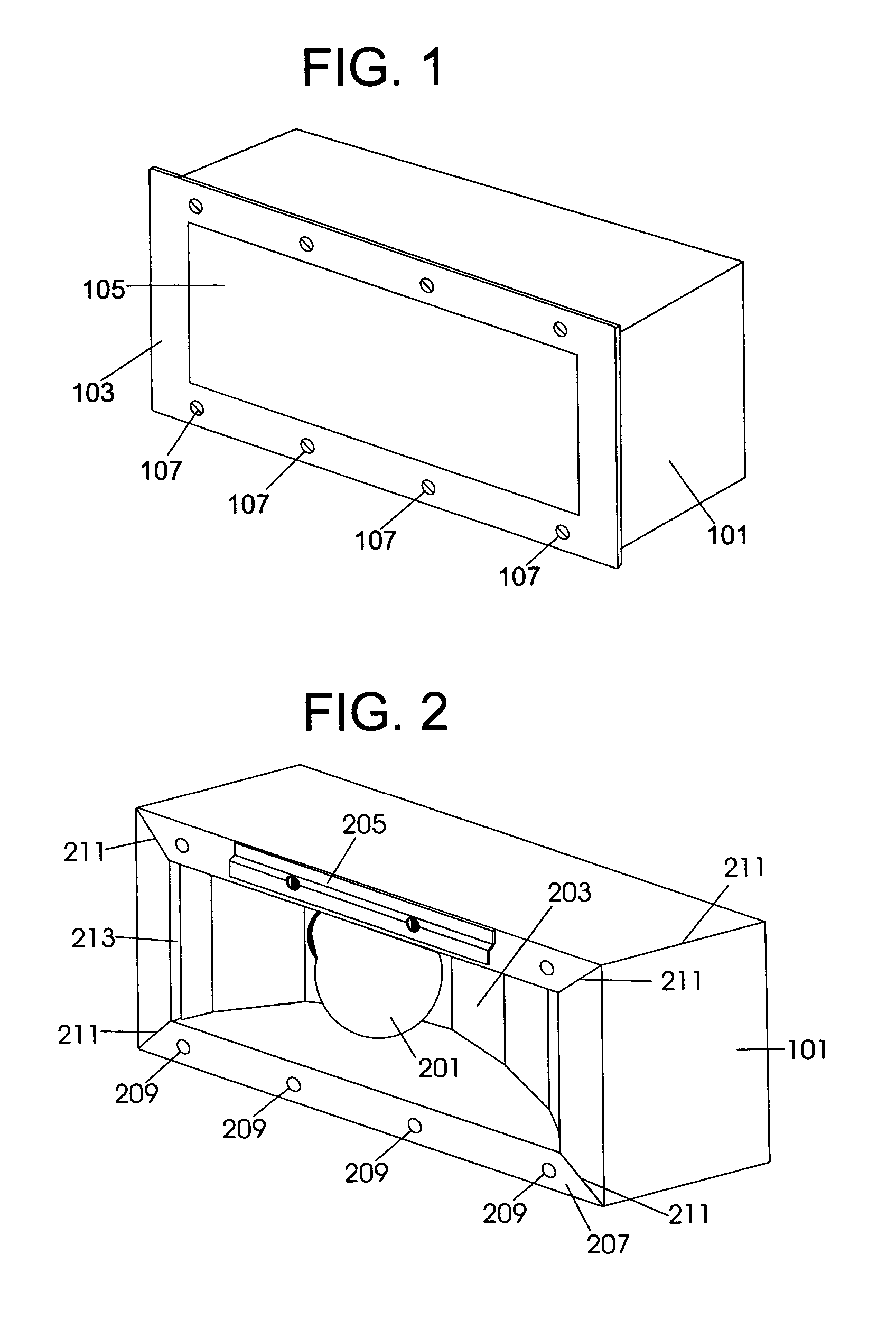
[0012]The following describes an apparatus including an enclosure in which a light source is disposed and which supports a part of the wall in which the apparatus is described. The enclosure may be disposed substantially within the wall, such that the enclosure does not provide an obstacle to those moving near the wall. Because the enclosure is capable of supporting a part of the wall, the enclosure may be substituted for one or more substructures of the wall, including, but not limited to, concrete blocks, cement blocks, bricks, cinder blocks, and combinations thereof. Because of its supporting nature, the enclosure may be disposed at most any height in the wall, and thus provides more direct light to the desired area.

Problems solved by technology

Either light source provides an obstacle to those moving near the walls.

Method used


Image

  • Enclosure for a light source
  • Enclosure for a light source
  • Enclosure for a light source

Examples


Embodiment Construction

[0012]The following describes an apparatus including an enclosure in which a light source is disposed and which supports a part of the wall in which the apparatus is described. The enclosure may be disposed substantially within the wall, such that the enclosure does not provide an obstacle to those moving near the wall. Because the enclosure is capable of supporting a part of the wall, the enclosure may be substituted for one or more substructures of the wall, including, but not limited to, concrete blocks, cement blocks, bricks, cinder blocks, and combinations thereof. Because of its supporting nature, the enclosure may be disposed at most any height in the wall, and thus provides more direct light to the desired area.

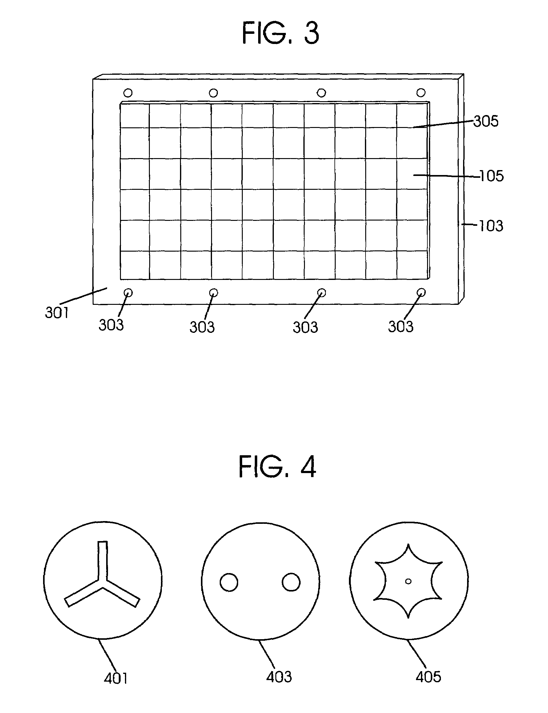
[0013]A perspective view of an enclosure 101 for a light source with a cover plate 103 is shown in FIG. 1. The enclosure 101 is typically shaped to mate with an opening in a wall. The enclosure is designed such that it is capable of supporting a part of the wall. As s...


PUM


Abstract

A light source is disposed in a cavity in an enclosure that supports a part of the wall. The enclosure may be disposed substantially within the wall, such that the enclosure does not provide an obstacle to those moving near the wall. Because the enclosure is capable of supporting a part of the wall, the enclosure may be substituted for one or more substructures of the wall, including, but not limited to, concrete blocks, cement blocks, bricks, cinder blocks, and combinations thereof. The enclosure may be disposed at most any height in the wall.

Description

FIELD OF THE INVENTION[0001]This invention relates to illumination, including, but not limited to, illumination sources disposed in walls.BACKGROUND OF THE INVENTION[0002]Illumination of areas adjacent to walls of buildings and other structures may be provided by light sources mounted to the walls or attached to freestanding structures near the walls. Either light source provides an obstacle to those moving near the walls. In addition, the light may be placed at a location that is higher or further away from the area to be lighted, thus the illumination source must be brighter, and thus utilize more power, to provide the desirable level of illumination.[0003]Accordingly, there is a need for a method and apparatus for illuminating an area on and / or near a wall without providing a significant obstacle next to the wall or requiring additional power to provide the desirable level of light.BRIEF DESCRIPTION OF THE DRAWINGS[0004]FIG. 1 is a perspective view of an enclosure for a light sou...

Claims


Application Information

Patent Timeline
Patent Type & Authority Patents(United States)
IPC IPC(8): F21S8/02F21V3/00F21V15/01F21V17/10F21V33/00
CPCF21S8/024F21V15/01F21V33/006F21V3/00F21V17/10F21Y2101/02F21Y2103/00F21V25/12F21Y2115/10
Inventor HELENOWSKI, JACEK
Owner HELENOWSKI JACEK
Learn More