LGA socket contact

a socket contact and land grid array technology, applied in the direction of fixed connections, coupling device connections, electrical apparatus construction details, etc., can solve problems such as unsuitable use in applications, and achieve the effect of reducing the arrangement pitch in this direction and minimizing the resistance of connection

Inactive Publication Date: 2005-12-20
TYCO ELECTRONICS JAPAN GK
View PDF12 Cites 72 Cited by
  • Summary
  • Abstract
  • Description
  • Claims
  • Application Information

AI Technical Summary

Benefits of technology

[0010]It is therefore an object of the invention to provide an LGA socket contact structured so that the size of a resilient contact in a direction perpendicular to a base plate in a vicinity of a root of the resilient contact is mini...

Problems solved by technology

The conventional contact 100, however, has the disadvantage that that it is unsuitable for use in applications wherein the engaging pins 104 and firs...

Method used


Image

  • LGA socket contact
  • LGA socket contact
  • LGA socket contact

Examples


first embodiment

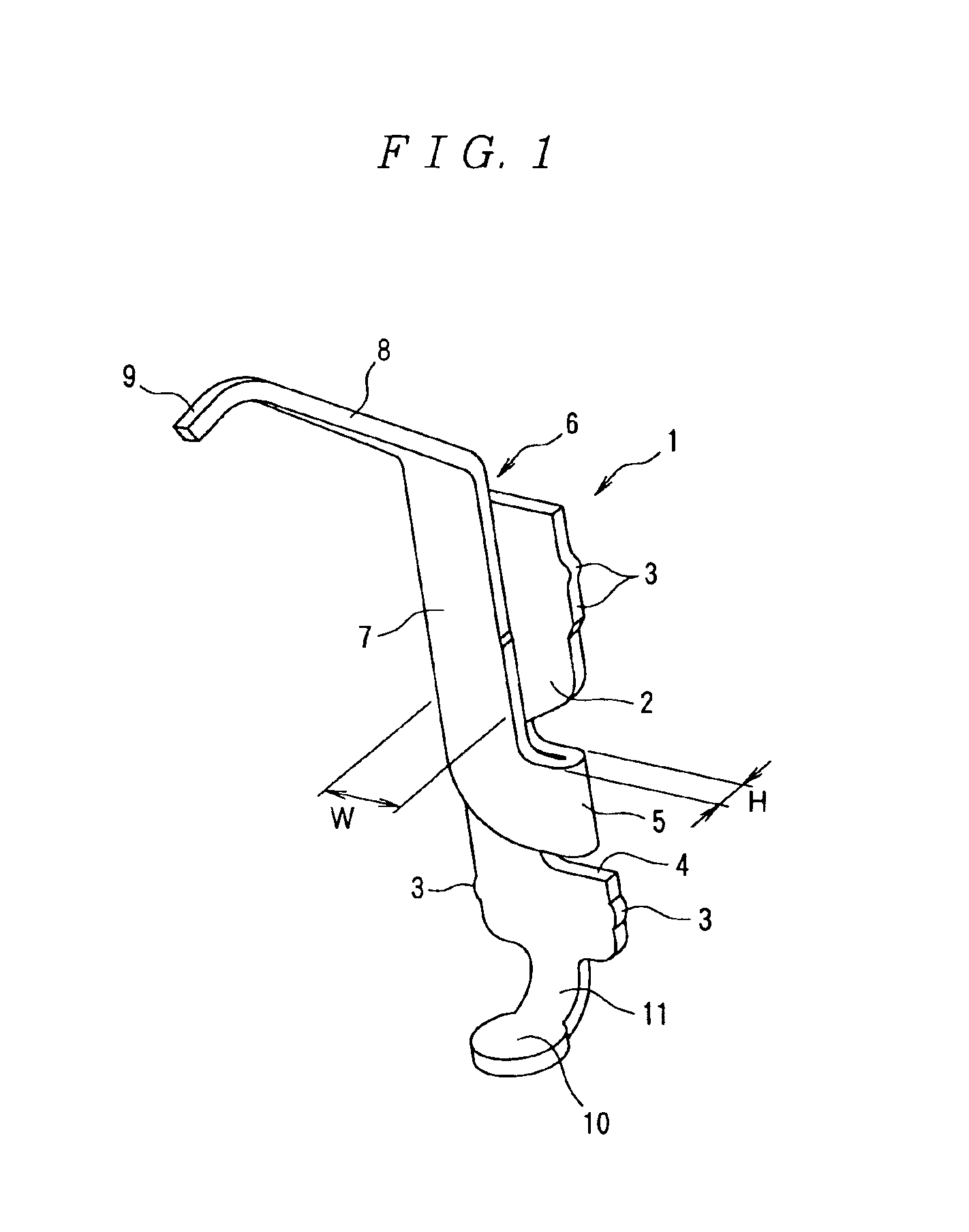
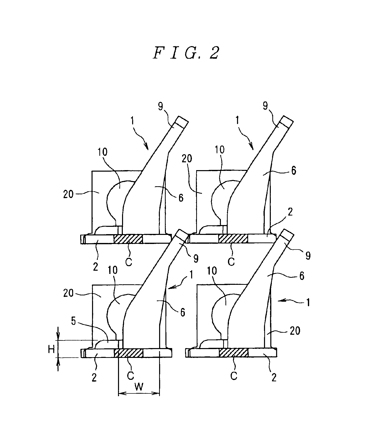
[0024]The invention will now be described in greater detail with reference to the figures. FIGS. 1 and 2 show an LGA socket contact (hereafter “contact”) 1. The contact 1 is formed by stamping and forming a metal plate and has a substantially rectangular base plate 2. A plurality of anchoring projections 3 is formed on each of two side walls of the base plate 2. Two of the anchoring projections 3 are formed on an upper portion of the base plate 2 and one of the anchoring projections 3 is formed on a lower portion of the base plate 2. The anchoring projections 3 are separated by a specified gap in a vertical direction. A cut-out 4 is formed in one of the side walls of the base plate 2 between the anchoring projections 3 of the upper portion and the anchoring projection 3 of the lower portion.

[0025]As best shown in FIG. 1, a resilient contact 6 is bent upward from a tip of a curved section 5 that is angled approximately 180 degrees from the cut-out 4. The resilient contact 6 has a fir...

second embodiment

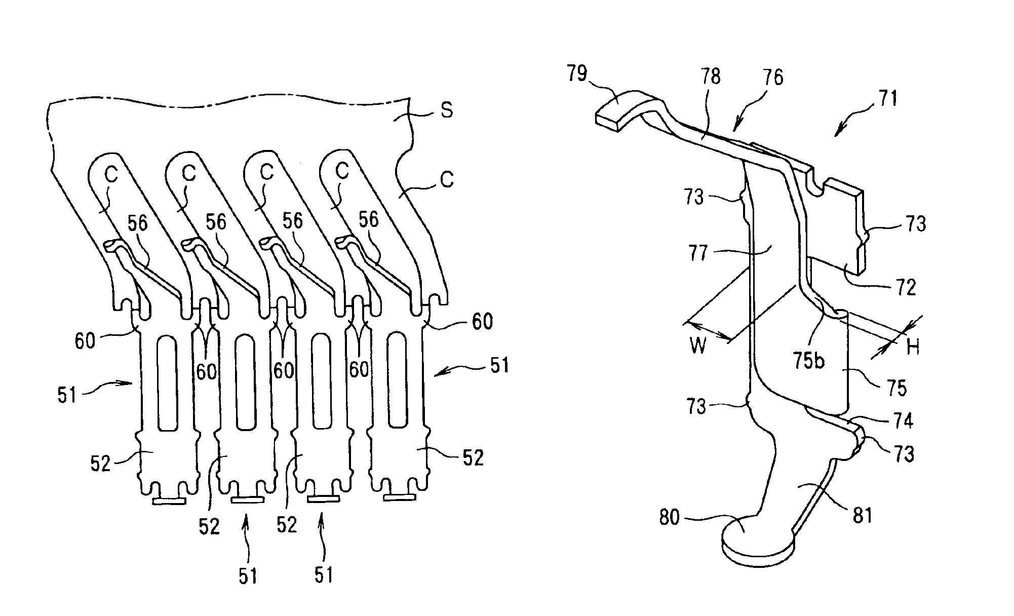
[0031]the LGA socket contact 51 of the invention will now be described with reference to FIGS. 3 through 5. The contact 51 is formed by stamping and forming a metal plate and has a substantially rectangular base plate 52, as shown in FIG. 3. A plurality of anchoring projections 53 is formed on each of two side walls of the base plate 52. One of the anchoring projections 53 is formed on an upper portion of the base plate 52 and one of the anchoring projections 53 is formed on a lower portion of the base plate 52. The anchoring projections 53 are separated by a specified gap in a vertical direction.

[0032]As best shown in FIG. 3, extending from the base plate 52 is an elastic plate portion 54. The elastic plate portion 54 has a width substantially the same as a width of the base plate 52, and front and back surfaces of the elastic plate portion 54 are coplanar with front and back surfaces of the base plate 52. Alternatively, the width of the elastic plate portion 54 may be different fr...


PUM


Abstract

A land grid array socket contact has a resilient contact that extends parallel to a base plate and is attached to at least one side walls of the base plate by a curved section angled approximately 180 degrees from the at least one side wall. The resilient contact has a free end for contacting a contact pad. A board terminal extends from a lower end of the base plate for connection to a circuit board. In another embodiment, the land grid array socket contact has a resilient contact extending from an upper end of a base plate. The resilient contact has an elongated slit substantially in a center of the resilient contact with respect to a direction of width and a free end for contacting a contact pad. A board terminal extends from a lower end of the base plate for connection to a circuit board.

Description

FIELD OF THE INVENTION[0001]The invention relates to a land grid array (LGA) socket contact for use in an LGA socket.BACKGROUND OF THE INVENTION[0002]LGA sockets are used to connect circuit boards with integrated circuit (IC) sockets that have a plurality of contact pads on a bottom surface thereof. FIGS. 7 and 8 illustrate a conventional contact 100 used in an LGA socket 120 (see U.S. Pat. No. 5,984,693). As shown in FIG. 7, the contact 100 is formed by stamping and forming a metal plate and has a substantially rectangular base plate 101. Guide projections 102 are formed on both ends of an upper edge 103 of the base plate 101 and protrude upward. Engaging pins 104 are formed on both ends of a lower edge of the base plate 101 and protrude downward. Two anchoring projections 105 are formed in positions that are separated by a specified distance in a vertical direction on each of two side walls of the base plate 101. An elastic C-shaped engaging portion 106 extends from between the en...

Claims


Application Information

Patent Timeline
IPC IPC(8): H01R33/76H01R4/48H01R13/24H05K7/10
CPCH01R13/2442H05K7/1069H01R12/52H01R12/714H01R12/57
Inventor SHIRAI, HIROSHIHASHIMOTO, SHINICHITAGUCHI, HIDENORI
Owner TYCO ELECTRONICS JAPAN GK
Why Eureka
Try Eureka