Anchoring structure for telescopic tubes of drum sets

a technology of telescopic tubes and drum sets, which is applied in the direction of stringed musical instruments, instruments, musical instruments, etc., can solve the problems of small compression area, easy deformation of inner tubes, and prone to shaking of telescopic tubes, so as to achieve more steady and less likely to be damaged

Active Publication Date: 2005-12-20
LIAO TSUN CHI
View PDF4 Cites 11 Cited by
  • Summary
  • Abstract
  • Description
  • Claims
  • Application Information

AI Technical Summary

Benefits of technology

[0005]Therefore the primary object of the invention is to provide a telescopic tube that can withstand the shock of the drum, and is more steady and less likely to be damaged when the length of the telescopic tube is adjusted.

Problems solved by technology

The compression area is small and is prone to loose.
When the drum 1 is struck for a long period of time and shock occurs constantly, the inner tube 4 is easily deformed and the telescopic tube 3 is prone to shaking.
However, in such a structure the inner tube 4 does not have any support while the fastening element 9 is unfastened, and the inner tube 4 often tilts abruptly.
As the drum 1 (referring to FIG. 1) supported by the inner tube is quite heavy, the inner tube 4 could be bent and result in adjustment difficulty later.
Moreover, the anchoring angle could be inaccurate and the sound generated by the drum 1 could be affected.

Method used


Image

  • Anchoring structure for telescopic tubes of drum sets
  • Anchoring structure for telescopic tubes of drum sets
  • Anchoring structure for telescopic tubes of drum sets

Examples


Embodiment Construction

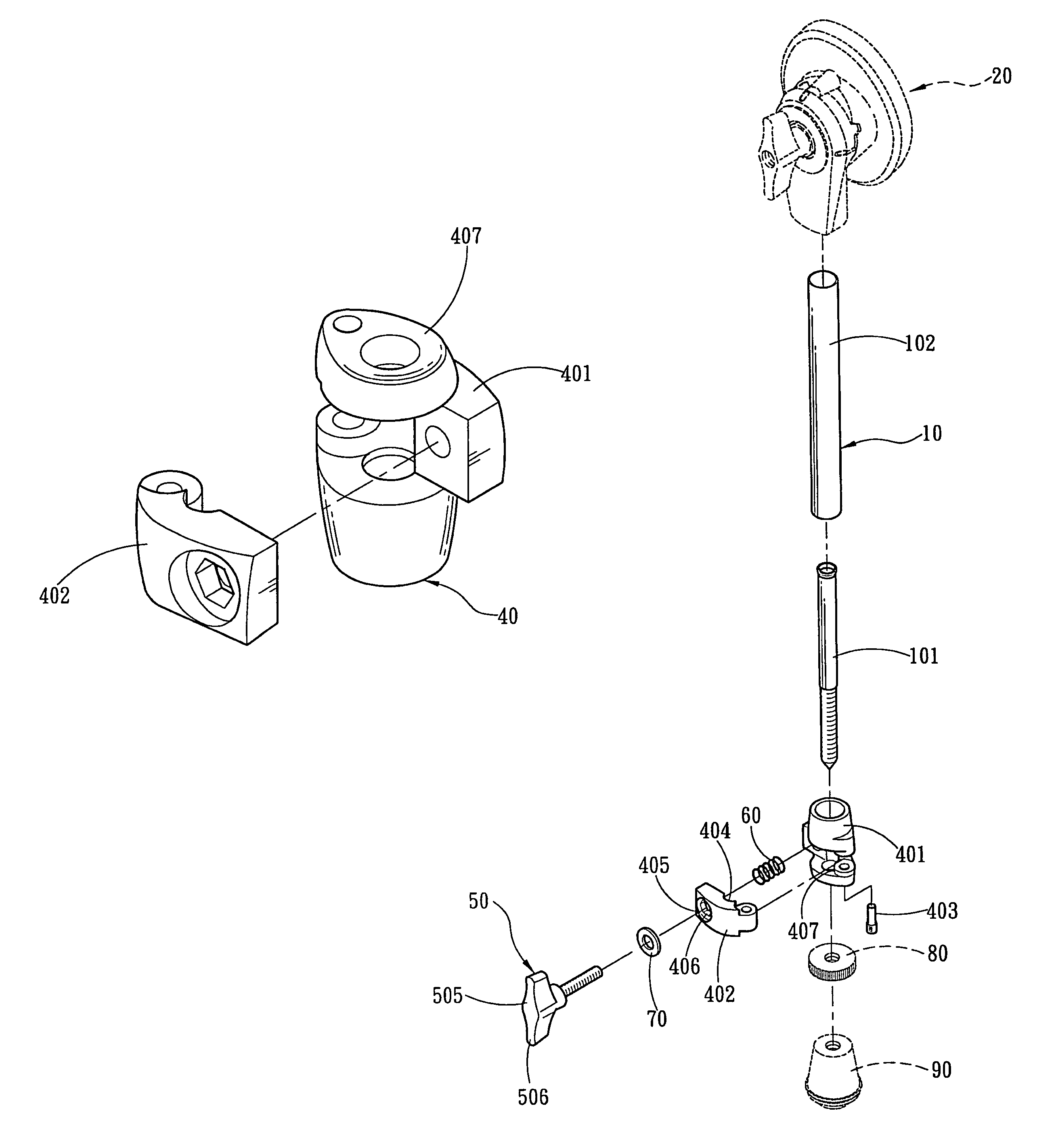
[0017]Please referring to FIGS. 4 and 5, the invention includes a telescopic tube 10 which consists of an inner tube 101 and an outer tube 102 that are coupled together. The telescopic tube 10 is coupled with a rotary dock 20 on one side to fasten to a drum (not shown in the drawings). The telescopic tube 10 has another side coupled with a buffer pad 90 and an adjustment ring 80 for standing on the floor. A fixing lock 40 is provided that consists of a fixing hub 401 and movable arm 402 that are coupled through a movable joint 403 such that they may be opened or closed like clam shells. The fixing hub 401 is coupled on the perimeter of one end of the outer tube 102. The fixing hub 401 and the movable arm 402 have respectively an arched trough 404 on a corresponding surface in the center to be in contact with the inner tube 101 and holds the inner tube 101. On the movable side of the fixing hub 401 and the movable arm 402, there is a fastening structure 405 (running through the fixin...


PUM


Abstract

A telescopic tube includes an inner tube and an outer tube. A fixing lock is provided that includes a fixing hub and a movable arm to couple with the perimeter of the outer tube. The fixing hub and the movable arm have respectively an arched trough on a corresponding surface in the center to clamp the inner tube. The fixing hub has a collar to couple with the inner tube. A drum may be steadily mounted and anchored on the telescopic tube. The telescopic tube may also be adjusted with a greater steadiness without shaking.

Description

FIELD OF THE INVENTION[0001]The present invention relates to an anchoring structure for drum sets and particularly to an anchoring structure for adjusting and setting the height of drum sets.BACKGROUND OF THE INVENTION[0002]Referring to FIGS. 1 and 2, the anchoring structure for a conventional drum 1 usually includes a rotary dock 2 located respectively on two sides to couple with a telescopic tube 3 for standing on the floor. The telescopic tube 3 has an inner tube 4 and an outer tube 5. A bolt 6 runs through the outer tube 5 to press the inner tube 4 to set the telescopic tube at a desired length. Users may unfasten and fasten the bolt 6 to adjust the length of the telescopic tube 3.[0003]The conventional technique for setting the telescopic tube 3 mentioned above relies on one bolt 6 to press the inner tube 4. The compression area is small and is prone to loose. When the drum 1 is struck for a long period of time and shock occurs constantly, the inner tube 4 is easily deformed an...

Claims


Application Information

Patent Timeline
Patent Type & Authority Patents(United States)
IPC IPC(8): B62D1/18G10D13/02
CPCG10D13/026G10D13/02G10D13/28
Inventor LIAO, TSUN-CHI
Owner LIAO TSUN CHI
Why Eureka
Try Eureka