Fuel injecton valve

Inactive Publication Date: 2007-01-04
ROBERT BOSCH GMBH +1
View PDF8 Cites 8 Cited by
  • Summary
  • Abstract
  • Description
  • Claims
  • Application Information

AI Technical Summary

Benefits of technology

[0010] The seal may be produced from a metallic material having an a

Problems solved by technology

Disadvantages of the fuel injector described in the European patent document EP 0 828 075 are the high demands regarding the accuracy of fit of the components and the complicated installation, which is involved and thus cost-intensive.
Particularly disadvantageous in the fuel injector described in published German

Method used


Image

  • Fuel injecton valve
  • Fuel injecton valve
  • Fuel injecton valve

Examples


Embodiment Construction

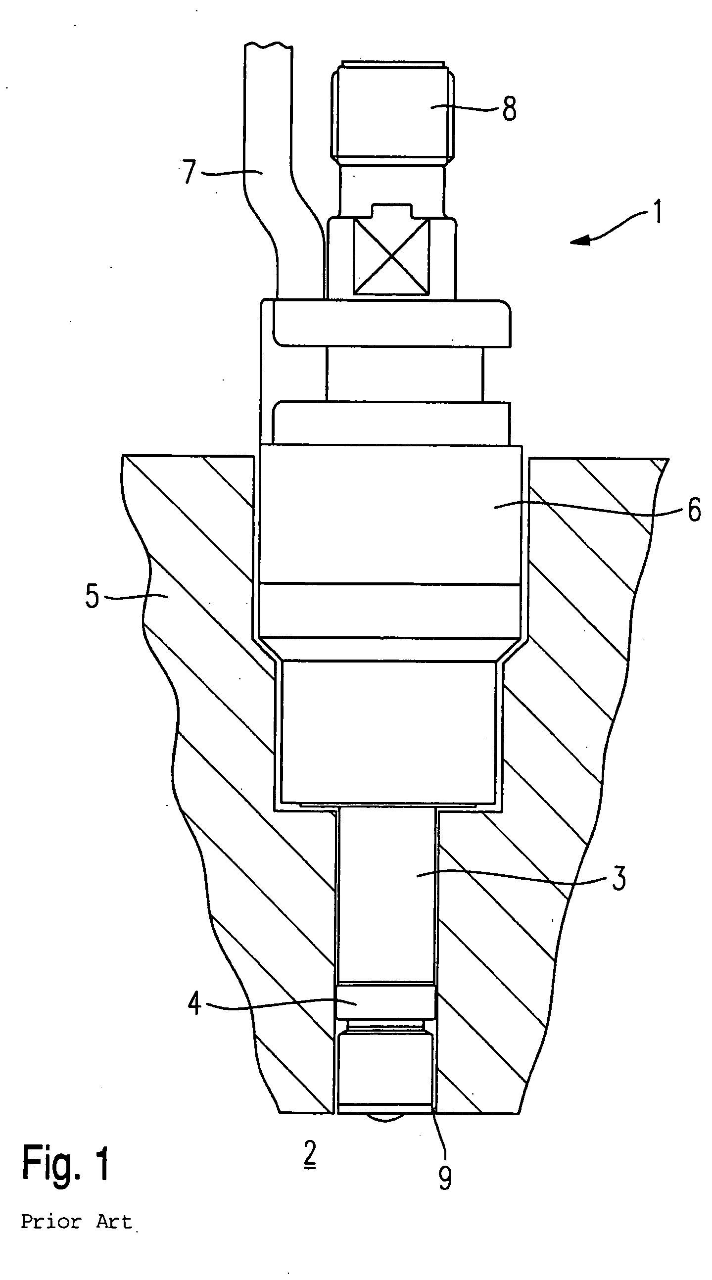
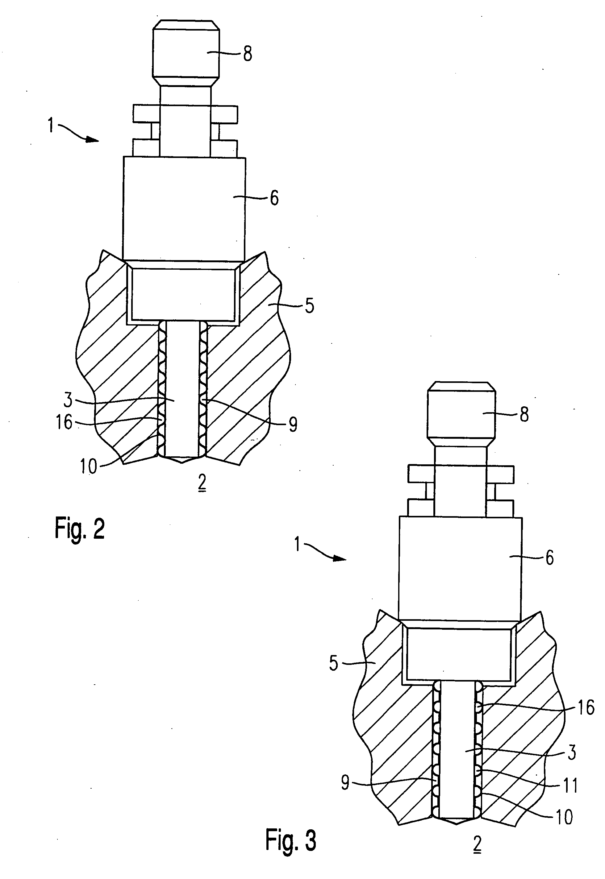
[0018] Before example embodiments of a fuel injector 1 according to the present invention are described in greater detail in connection with FIGS. 2 through 7, for a better understanding of the present invention, a conventional fuel injector 1 will be briefly explained in terms of its essential components on the basis of FIG. 1.

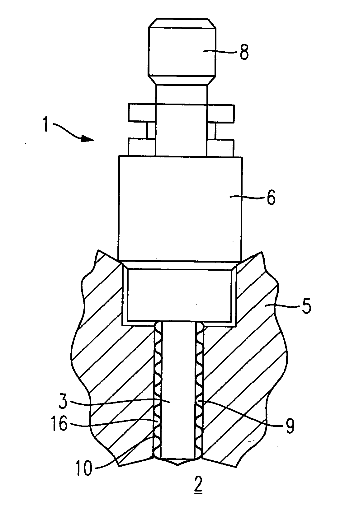
[0019] Fuel injector 1 is configured for fuel-injection systems of mixture-compressing internal combustion engines with externally supplied ignition. Fuel injector 1 is suited, e.g., for the direct injection of fuel into a combustion chamber 2 of an internal combustion engine.

[0020] Fuel injector 1 includes a nozzle body 3, which is sealed from a cylinder head 5 of the internal combustion engine by a sealing ring 4. Sealing ring 4 is made of, for instance, an elastomeric material such as a Teflon-coated material and provides the sealing effect in cylinder head 5 as a result of a slightly larger diameter compared to nozzle body 3.

[0021] Furthermore, fuel in...


PUM


Abstract

A fuel injector for the direct injection of fuel into the combustion chamber of a mixture-compressing internal combustion engine having external ignition includes a valve housing formed by a nozzle body, and a seal which seals the fuel injector from a cylinder head of the internal combustion engine. The seal has a sleeve-type design with a structured cross section and extends across the axial length of the nozzle body.

Description

FIELD OF THE INVENTION [0001] The present invention relates to a fuel injector for direct injection of fuel, which fuel injector is provided with a seal. BACKGROUND INFORMATION [0002] Published European patent document EP 0 828 075 describes a fuel injector for the direct injection of fuel into the combustion chamber of an internal combustion engine, which has a device for adjusting the temperature in the region of the valve tip so as to reduce deposits in this area. The device is embodied in the form of a coating made of a thermally conductive material on the valve tip. [0003] Disadvantages of the fuel injector described in the European patent document EP 0 828 075 are the high demands regarding the accuracy of fit of the components and the complicated installation, which is involved and thus cost-intensive. [0004] Furthermore, a fuel injector for the direct injection of fuel into the combustion chamber of a mixture-compressing internal combustion engine having external ignition is...

Claims


Application Information

Patent Timeline
IPC IPC(8): F02M61/14F02M53/04
CPCF02M61/14F02M53/04
Inventor HOENIG, GUENTERWUERFEL, GERNOTNOWAK, DETLEFMLEJNEK, ANDREASROESSLER, KLAUS
Owner ROBERT BOSCH GMBH
Why Eureka
Try Eureka