Sensor bracket

a technology of sensor brackets and brackets, which is applied in the direction of camera filters, instruments, vehicle components, etc., can solve the problems of needing replacement and unstable up-down direction of the camera body on the camera, and achieve the effect of preventing damage and ensuring reliability

Active Publication Date: 2017-09-28
HONDA MOTOR CO LTD
View PDF4 Cites 6 Cited by
  • Summary
  • Abstract
  • Description
  • Claims
  • Application Information

AI Technical Summary

Benefits of technology

[0014]According to such a configuration, when the operator dismounts the spring member from the spring mount portion, by displacing the tool towards a direction in which the tool comes in contact with the displacement restriction portion, the windshield and the like can be reliably prevented from becoming damaged.

Problems solved by technology

Since the flat spring of Japanese Unexamined Patent Application Publication No. 2013-203250 biases the on-board camera body only in the front direction, the on-board camera body may be unstable in the up-down direction.
However, in Japanese Unexamined Patent Application Publication No. 2013-203250, since the flat spring is integral with the bracket, when there is a defect in the flat spring, the bracket and all need to be replaced.

Method used


Image

  • Sensor bracket
  • Sensor bracket
  • Sensor bracket

Examples


Embodiment Construction

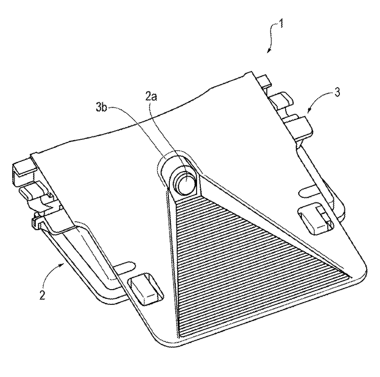
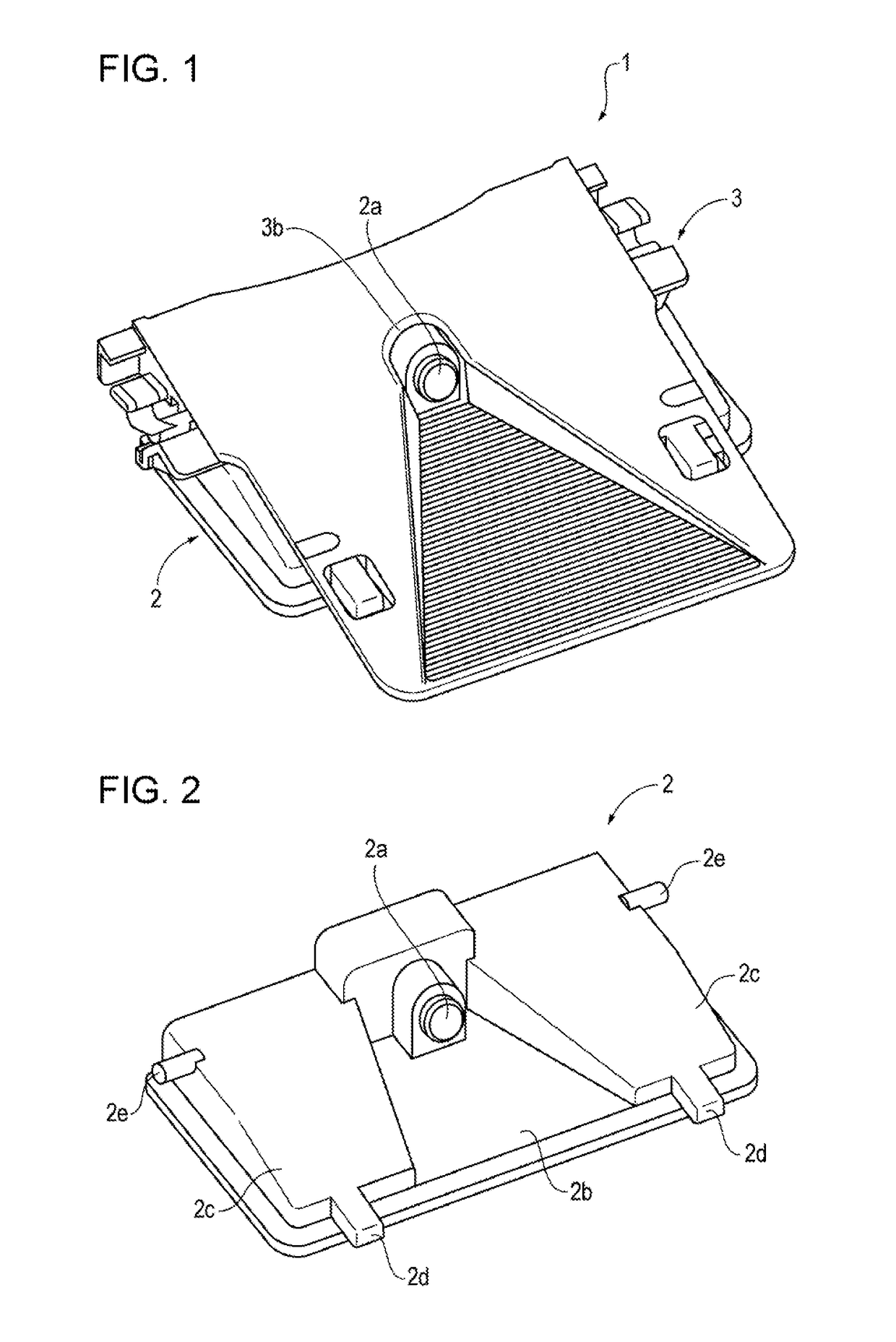
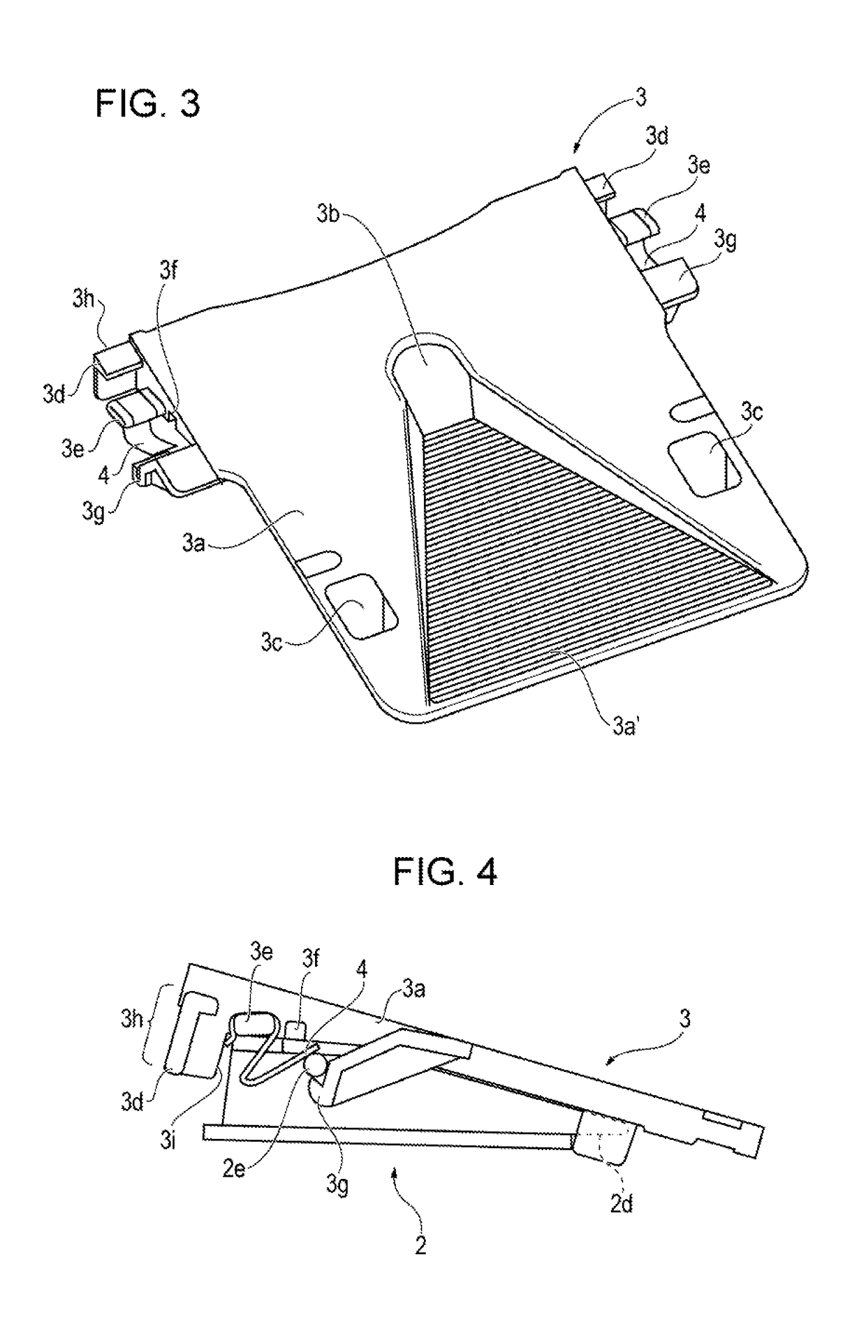
[0021]FIG. 1 illustrates a configuration in which a camera corresponding to a sensor of the present disclosure that detects the surroundings of a vehicle is mounted on a sensor bracket of the present disclosure. Hereinafter, the above configuration is referred to as a camera unit 1.

[0022]FIG. 1 is a perspective view of the camera unit 1 viewed obliquely from above. The camera unit 1 includes a camera 2 that is a sensor that performs imaging of an image in front of the vehicle, and a bracket 3 that is fixed to the windshield of the vehicle by being adhered thereon. Note that, hereinafter, description is given while the front of the vehicle is a front direction (a front side).

[0023]As illustrated in the drawings, the camera 2 is mounted on the bracket 3 from a lower side of the bracket 3 with an engaging mechanism described later. An opening 3b into which a lens 2a of the camera 2 is inserted is provided on an upper surface of the bracket 3. With the above, the camera 2 is capable of ...


PUM


Abstract

A sensor bracket includes a bracket on which a camera (a sensor) that detects a state around a vehicle is mounted, a flat spring that abuts against the camera in a direction that maintains a mounted state of the camera when the camera is mounted on the bracket, and a stopper restricting, in between a space where a tool is positioned and an inner surface of a piece of glass, a displacement range of the tool from the space to the inner surface of the piece of glass when the flat spring is dismounted from a projection for the spring of the bracket with the tool.

Description

CROSS REFERENCES TO RELATED APPLICATIONS[0001]The present application claims priority under 35 U.S.C. §119 to Japanese Patent Application No. 2016-060375, filed Mar. 24, 2016, entitled “Sensor Bracket.” The contents of this application are incorporated herein by reference in their entirety.BACKGROUND1. Field[0002]The present disclosure relates to a sensor bracket used to attach an on-board camera or the like.2. Description of the Related Art[0003]Hitherto, a technique is known that accurately detects an obstacle and a pedestrian, a position of a traffic lane, whether a headlight of an oncoming vehicle is on, and the like by performing imaging of a portion in front of a vehicle with an on-board camera. In such a case, the on-board camera is mounted on a bracket that is attached to a windshield.[0004]For example, in Japanese Unexamined Patent Application Publication No. 2013-203250, while bosses of an on-board camera main body are hooked to hook-shaped portions, the on-board camera ma...

Claims


Application Information

Patent Timeline
Patent Type & Authority Applications(United States)
IPC IPC(8): B60R11/04F16M13/02G03B17/56
CPCB60R11/04B60R2011/0043F16M13/02G03B17/561B60R2011/0026B60R2011/0071B60R2011/0075B60R2011/0078G03B11/045
Inventor KASAI, KEITATOKIWA, MITSURUMATORI, TADAHIROOHMOTO, TAKAHIRO
Owner HONDA MOTOR CO LTD
Why Eureka
Try Eureka