Head-mounted optical direct visualization system

a technology of optical direct visualization and headmounted optical projection, which is applied in the field of headmounted optical direct projection system, can solve the problems of not being user-friendly or application-friendly, and achieve the effect of optimizing the quality and the size of the virtual imag

Inactive Publication Date: 2005-12-20
CARL ZEISS AG
View PDF8 Cites 113 Cited by
  • Summary
  • Abstract
  • Description
  • Claims
  • Application Information

AI Technical Summary

Benefits of technology

[0008]This possibility according to the invention for changing the position of the optical end element and therefore for changing the position at which the user receives the reflected-in virtual image within his viewing field offers the following advantages. On the one hand, an adaptation of this position to the individual head dimensions and to the individual eye position of the user is possible. On the other hand, the position of the virtual image can be adapted to the individual eye behavior of the user as well as to the instantaneous task-specific primary direction. The latter takes place preferably with the aid of a tracking system.
[0009]Advantageously, the optical end element is configured as a prism. This affords the advantage that the prism is half light permeable so that, on the one hand, it makes possible making the virtual image available forward of the eye of the user but, on the other hand, also does not entirely block the view of the user to the real world.
[0010]Advantageously, the deflection device (especially, a lens system contained therein) and / or the size of the prism as end element can be variably selected for the purpose of optimizing the quality and size of the virtual image.
[0011]Likewise for optimizing the quality and the size of the virtual image, it is further advantageous when the surfaces of the optical end element and / or of an optical deflecting element in the deflecting device are each configured as a prism, at least partially convex or concave curved.
[0012]The head-mounted direct visualization system according to the invention can include, in addition to a first deflecting device, also a second deflecting device having a second optical end element for deflecting a second virtual image, which is generated by a second image source, to the second optical end element. In this way, the possibility is provided for fading in a second virtual image in front of the eyes of the user. Advantageously, but not absolutely necessary, the first and second optical end elements are mounted in front of different eyes of the user. In this way, a binocular is realized which makes possible either a single view or a stereo view for the user.
[0013]When the frame for carrying the optical deflecting device is configured as a spectacles frame with spectacle lenses, which are suitable for the user, this affords the advantage that, in a simple manner, the defective vision of the user is corrected by the spectacle lenses not only when viewing the real world but also when viewing the virtual image.

Problems solved by technology

A known head-mounted direct visualization system of this kind has, however, the disadvantage that it is not very user friendly or application friendly.

Method used


Image

  • Head-mounted optical direct visualization system
  • Head-mounted optical direct visualization system

Examples


Embodiment Construction

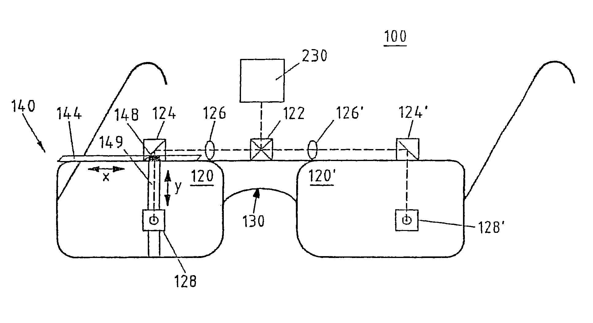
[0018]FIG. 1 shows a head-mounted optical visualization system 100 in accordance with the invention. The system includes an optical deflecting device 120 for deflecting a virtual image, which is generated by an image source 230, into the viewing field of a user. For this purpose, the deflecting device 120 preferably includes optical deflecting elements (122, 124) for deflecting the virtual image to an optical end element 128 which is likewise a component of the optical deflecting system 120. The optical deflecting elements (122, 124) are configured as prisms and the virtual image is generated by the image source 230. The virtual image exits through the optical end element 128 into the viewing field of the user ahead of the eyes of the user. The deflecting device is usually mounted on the head of the user with the aid of a frame 130. The deflecting device 120 further includes a lens or a lens system 126 for realizing an optimal image sharpness.

[0019]According to the invention, an adj...


PUM


Abstract

A head-mounted optical direct visualization system has at least one optical deflecting device (120) with an optical end element (128) for deflecting a virtual image generated by an image source (230) onto the optical end element (128). The virtual image is emitted through the optical end element into the field of view in front of the eyes of the user. The optical deflecting device (120) is attached to the head of the user with the aid of a frame (130). The task of the invention is to configure such a conventional direct visualization system so as to be better adaptable to the requirements of the anatomical and optical features of the user and the application-specific viewing requirements. This task is solved with an adjusting device (140), which is fixed to the frame (130), for variably changing the position of at least the optical end element (128) essentially in a plane parallel to the field of view of the user.

Description

RELATED APPLICATIONS[0001]This application is a continuation application of international patent application PCT / EP 02 / 06482, filed Jun. 13, 2002, and claiming priority from German patent application 101 32 872.9, filed Jul. 6, 2001. International application PCT / EP 02 / 06482 and German patent application 101 32 872.9 are both incorporated herein by reference.FIELD OF THE INVENTION[0002]The invention relates to a head-mounted optical direct visualization system (head-mounted display (HMD)).[0003]Accordingly, a head-mounted direct visualization system includes at least one optical deflecting device 210 which, with the aid of a frame 220, is mounted on the head of a user (see FIG. 2). A head-mounted direct visualization system is known from the state of the art, especially from U.S. Pat. No. 5,886,822. The optical deflecting device 210 includes an optical end element 215 and functions to deflect a virtual image, which is generated by an image source 230, to the optical end element 215....

Claims


Application Information

Patent Timeline
Patent Type & Authority Patents(United States)
IPC IPC(8): G02B27/02G02B27/00G02B27/01H04N5/64
CPCG02B27/0172G02B27/0176G02B2027/0132G02B2027/0136G02B2027/0178
Inventor VOLKENANDT, HARALDFREY, UWEALT, THOMASSCHREIBER, WERNER
Owner CARL ZEISS AG
Why Eureka
Try Eureka