AI technical title is built by Patsnap AI team. It summarizes the technical point description of the patent document.
a technology for wiper blades and windows, which is applied in the direction of vehicle maintenance, vehicle cleaning, domestic applications, etc., can solve the problems of high cost, inconvenient installation, and inconvenient operation, and achieves cost reduction, easy operation, and simple installation movement.
Inactive Publication Date: 2005-12-27
ROBERT BOSCH CORP
View PDF24 Cites 54 Cited by
Summary
Abstract
Description
Claims
Application Information
AI Technical Summary
This helps you quickly interpret patents by identifying the three key elements:
Problems solved by technology
Method used
Benefits of technology
Benefits of technology
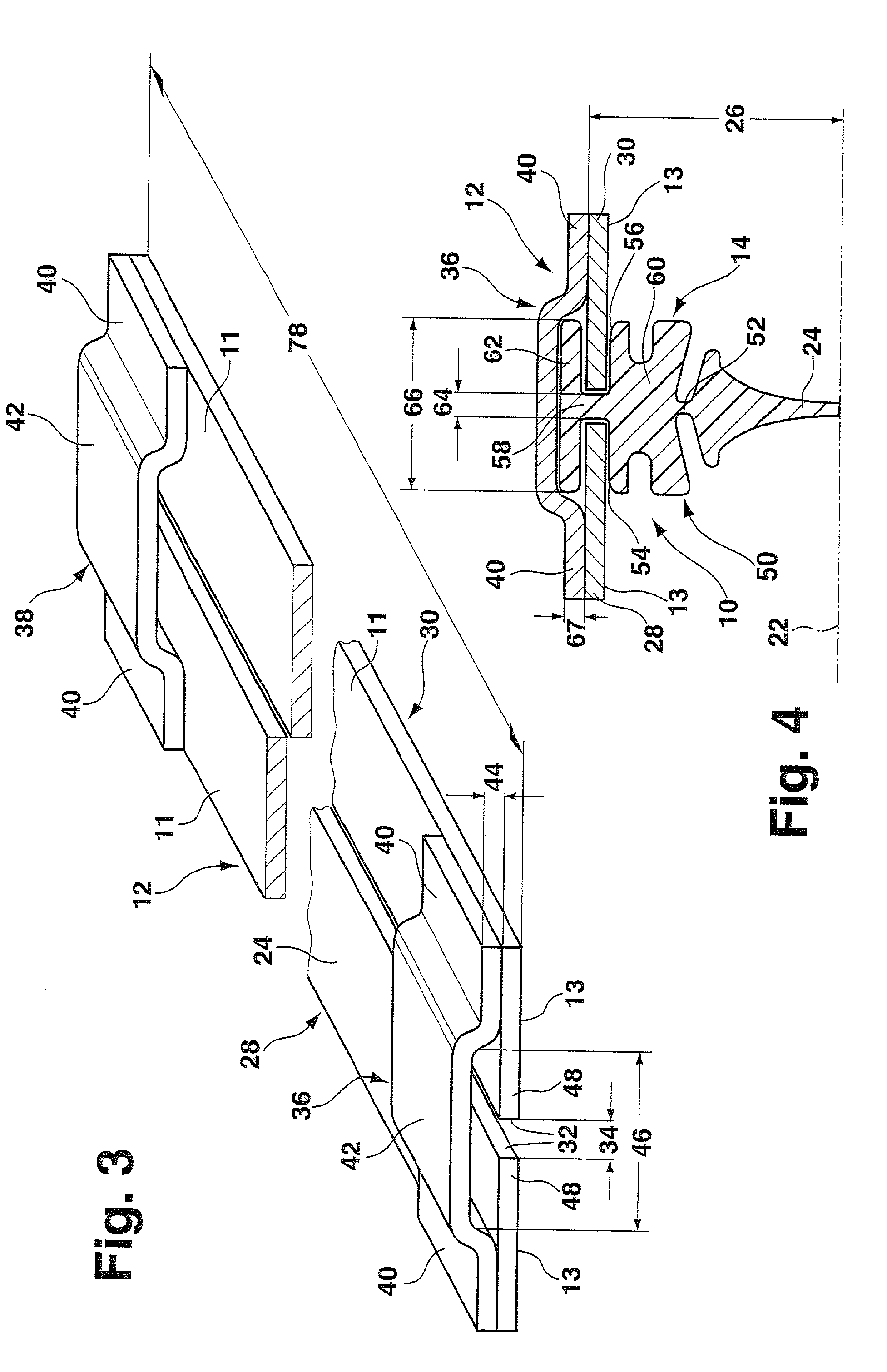
[0003]In the wiper blade according to the invention, with the characterizing features of claim 1, it is possible, starting from one end of the support element, to insert the wiper strip in a rectilinear fashion between the two opposing longitudinal edges of the spring strip, where their inner, free edge strips protrude into the longitudinal grooves of the wiper strip. This simple installation movement can be easily executed by an automated installation machine, which achieves a considerable cost reduction. In addition, the disadvantageous installation opening of the slot can be eliminated because the bridge-like crosspieces permit the rectilinear installation motion of the wiper strip from one end of the support element.
[0004]Embodying the crosspieces as separate components that are attached to the spring strips achieves advantages in the production of the wiper blade.
Problems solved by technology
This installation opening, though, can produce disadvantageous changes in the spring properties of the support element with regard to the desired wiping results.
In addition, manually inserting the wiper strip into the slot through this opening is cost-intensive.
Method used
Image
Click on the blue label to locate the original text in one second.
Reading with bidirectional positioning of images and text.
Examples
Embodiment Construction
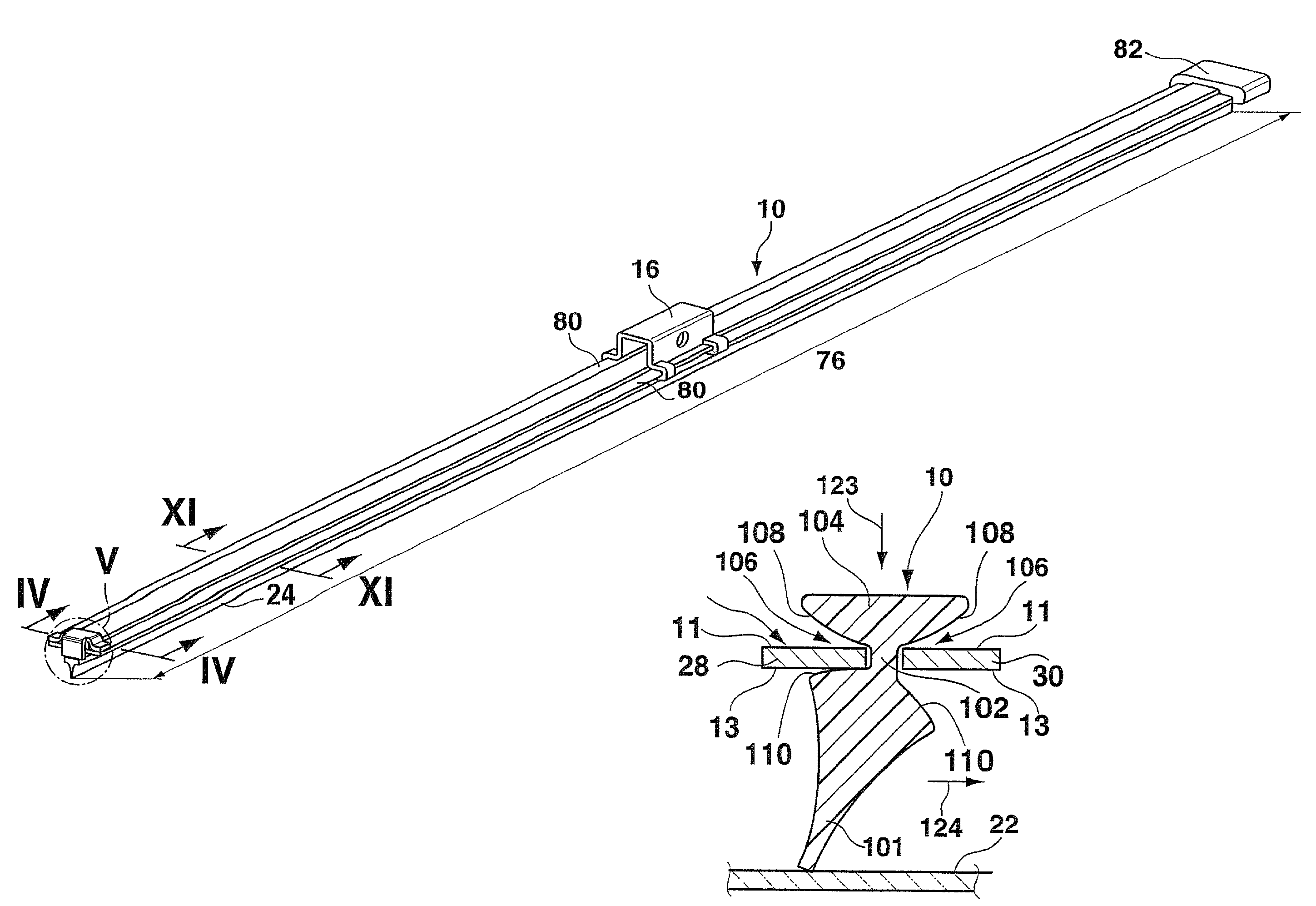
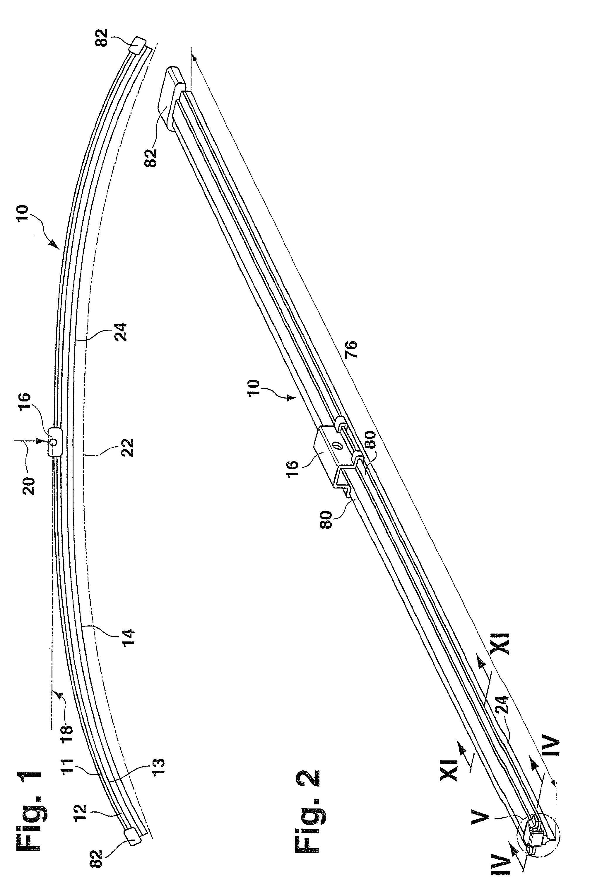
[0032]A wiper blade 10 indicated in FIGS. 1 and 2 has a band-like, elongated, spring-elastic support element 12, against whose underside 13 an elongated, rubber-elastic wiper strip 14 is disposed so that their longitudinal axes are parallel. On the top side 11 of the support element 14, which is also referred to as a spring bar, the center section of the support element is provided with the wiper blade part 16 of a connecting device, with the aid of which the wiper blade 10 can be detachably connected in an articulating fashion to a driven wiper arm 18 indicated with a dot-and-dash line in FIG. 1. To that end, the free end of the wiper arm 18 is provided with the wiper arm part of the connecting device. The wiper arm 18 is loaded in the direction of the arrow 20 toward the window to be wiped, for example the windshield of a motor vehicle, whose surface to be wiped is indicated with a dot-and-dash line 22 in FIG. 1. Since the line 22 is intended to represent the sharpest curvature of...
PUM
Abstract
A wiper blade is proposed, which is for cleaning for windows, particularly of motor vehicles. The wiper blade (10) has an elongated, rubber-elastic wiper strip (14), which can be placed against the window (22) and is connected to an elongated, spring-elastic support element (12) so that their longitudinal axes are parallel, which support element (12) is directly connected to a device (16) for connecting the wiper blade to a driven wiper arm (18). The support element (12) has two band-like spring strips (28, 30), which are situated in a plane that is disposed in front of the window, essentially parallel to the window, and whose one, lower band surfaces (13) are oriented toward the window and whose adjacent, inner longitudinal edges (48), which are disposed spaced a distance (34) apart from each other, each protrude into a respective longitudinal groove (54, 56, or 106), which grooves are associated with each longitudinal edge and are open toward a respective longitudinal side of the wiper strip (14), and these two spring strips (36, 38) are connected to each other by at least two crosspieces (36, 38) disposed spaced apart from each other in the longitudinal direction. Manufacturing advantages for the wiper blade according to the invention are achieved if each crosspiece (36, 38) has a middle section (42) which extends spaced a distance (44) apart from the upper band surfaces (11) of the spring strips (28, 30), producing bridge-like crosspieces, where the distance (34) between the two longitudinal strips (28, 30) is less than the bridge width (46).
Description
BACKGROUND OF THE INVENTION[0001]In common wiper blades for motor vehicles, the purpose of the support element is to assure as uniform as possible a distribution of the wiper blade pressure against the window, which pressure is exerted by a wiper arm connected to the wiper blade, over the entire wiping field wiped by the wiper blade. Through an appropriate curvature of the unloaded support element—i.e. when the wiper blade is not resting against the window—the ends of the wiper strip, which is placed completely against the window during the wiping operation of the wiper blade, are loaded toward the window by the support element, which is under tension in this state, even though the curvature radii of spherically curved vehicle windows change with each wiper blade position. The curvature of the wiper blade must therefore be somewhat sharper than the sharpest curvature measured within the wiping field on the window to be wiped. The support element consequently replaces the complex sup...
Claims
Application Information
Patent Timeline
Application Date:The date an application was filed.
Publication Date:The date a patent or application was officially published.
First Publication Date:The earliest publication date of a patent with the same application number.
Issue Date:Publication date of the patent grant document.
PCT Entry Date:The Entry date of PCT National Phase.
Estimated Expiry Date:The statutory expiry date of a patent right according to the Patent Law, and it is the longest term of protection that the patent right can achieve without the termination of the patent right due to other reasons(Term extension factor has been taken into account ).
Invalid Date:Actual expiry date is based on effective date or publication date of legal transaction data of invalid patent.

