Apparatus for fusing adjacent bone structures

a bone structure and applicator technology, applied in the field of adjacent bone structure fusion, can solve the problems of painful disc translocation and mechanical instability, and achieve the effects of improving spinal fusion devices and procedures, facilitating fusion, and enhancing fusion

a bone structure and applicator technology, applied in the field of adjacent bone structure fusion, can solve the problems of painful disc translocation and mechanical instability, and achieve the effects of improving spinal fusion devices and procedures, facilitating fusion, and enhancing fusion

US6979353B2Inactive Publication Date: 2005-12-27HOWMEDICA OSTEONICS CORP

Image

  • Apparatus for fusing adjacent bone structures
  • Apparatus for fusing adjacent bone structures
  • Apparatus for fusing adjacent bone structures

Examples


Embodiment Construction

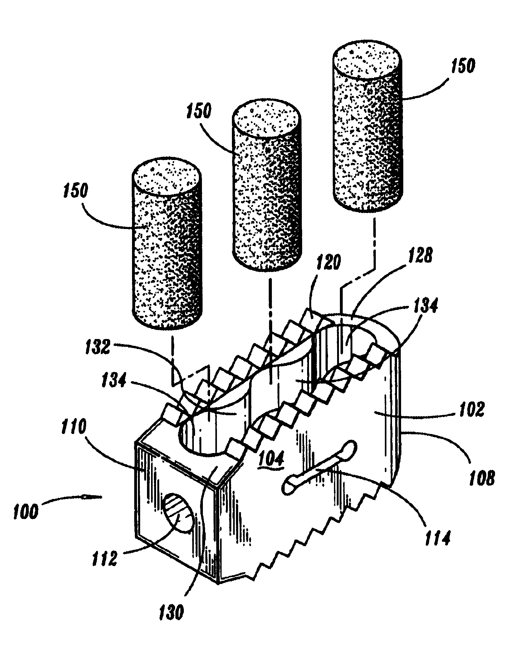
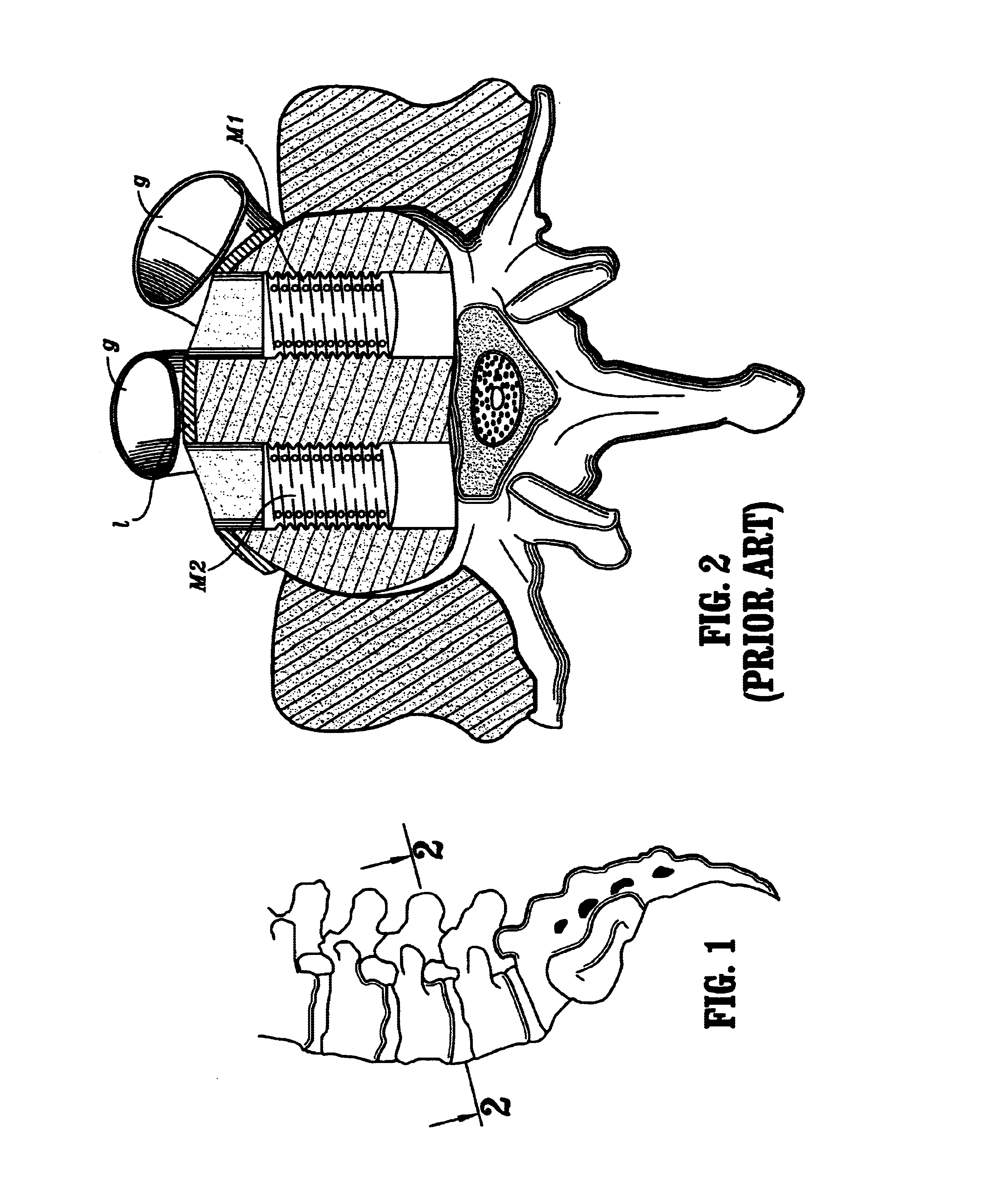
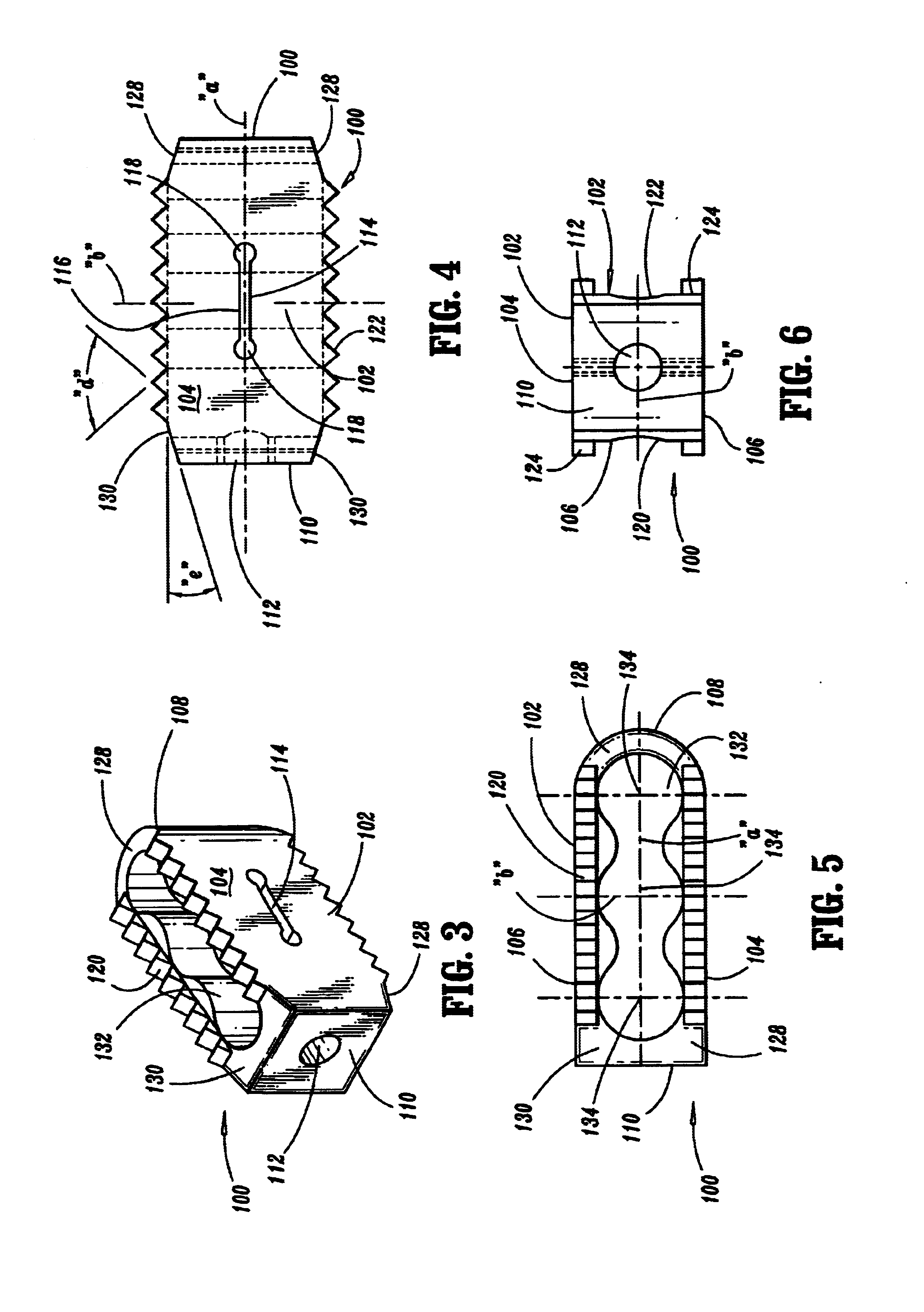
[0026]A preferred embodiment of the apparatus and method disclosed herein are discussed in terms of orthopedic spinal fusion procedures and instrumentation. It is envisioned, however, that the disclosure is applicable to a wide variety of procedures including, but, not limited to ligament repair, joint repair or replacement, non-union fractures, facial reconstruction and spinal stabilization. In addition, it is believed that the present method and instrumentation finds application in both open and minimally invasive procedures including endoscopic and arthroscopic procedures wherein access to the surgical site is achieved through a cannula or small incision.

[0027]The following discussion includes a description of a fusion implant utilized in performing a spinal fusion followed by a description of the preferred method for spinal fusion in accordance with the present disclosure.

[0028]In the discussion which follows, the term “proximal”, as is traditional, will refer to the portion of ...


PUM

PropertyMeasurementUnit
Flexibilityaaaaaaaaaa
Shapeaaaaaaaaaa

Abstract

An apparatus for facilitating fusion of adjacent vertebrae includes an implant body dimensioned for positioning within an intervertebral space between upper and lower vertebrae to maintain the vertebrae in desired spaced relation to facilitate fusion thereof. The implant body includes lower and upper surfaces for engaging the respective lower and upper vertebrae and first and second side wall portions extending between the upper and lower surfaces. The first and second side wall portions are substantially solid. At least one of the first and second side wall portions have a substantially narrow longitudinal slit defined therein arranged to enhance flexibility of the one side wall portion. Preferably, each of the first and second side wall portions includes a longitudinal slit. The implant body may define an internal chamber dimensioned for reception of bone growth inducing substances. The implant body includes an internal bore extending through the upper and lower surfaces for reception of bone growth inducing substances. Preferably, the internal bore is cylindrical shaped to receive a cylindrical bone dowel harvested during the surgical procedure, or alternatively, to receive a prepackaged cylindrical rod containing bone growth inducing substances. A plurality of internal bores may be provided in side by side relation.

Description


Claims


Application Information

Patent Timeline
27 Dec 2005
Publication
US6979353B2