Delay line synchronizer apparatus and method

a synchronizer and delay line technology, applied in the direction of generating/distributing signals, pulse techniques, instruments, etc., can solve the problems of different time delays, line loading problems, propagation delays,

Inactive Publication Date: 2005-12-27
ROUND ROCK RES LLC
View PDF224 Cites 72 Cited by
  • Summary
  • Abstract
  • Description
  • Claims
  • Application Information

AI Technical Summary

Problems solved by technology

For example, phase shifts can result from line loading issues, varying line impedances, and propagation delays.
Another example is different lengths of different conductive signal paths will cause different time delays.
Thus, two synchronized clock signals on two different length signal paths will have two different time delays, and consequently, arrive at their respective destinations at different times. Where an operation relies on the synchronization of the two clock signals, clearly this situation is undesirable.
The added time delay to a clock signal causes the clock signal to shift in time, thus, resulting in the phase of the delayed clock signal shifting.
A problem related to conventional delay circuits is that glitch or runt pulses are often output from the delay circuit in response to changing the time delay.
In some cases, the particular design of the delay circuit is inherently susceptible to generating glitch pulses when the time delay is changed.
Factors such as the timing of an input clock signal relative to when a delay circuit is disabled in order to change the time delay or switching noise also contribute to the generation of glitch pulses.
The problem results from the possibility that the glitch pulses may inadvertently trigger a response by a circuit coupled to the output of the delay circuit.
Thus, when changing the time delay of a delay circuit, an errant pulse may cause unexpected results.
Another problem with using conventional delay lines arises with respect to maintaining a phase relationship between a first clock signal and a second, higher frequency clock signal, when adjusting the time delay of a delay line circuit used in delaying the second clock signal.
In the process of adjusting the time delay of the delay circuit, the phase relationship of the second clock signal relative to the first clock signal may be lost.
More specifically, a circuit that performs a function in response to the second clock signal, that results in performing the function generally coincident with a clock transition of the first clock signal, can end up performing the function at the wrong time with respect to the first clock signal because the phase relationship of the second clock signal changes relative to the first clock signal is lost when the time delay is adjusted.
Additionally, where other circuitry in the memory device or a memory controller coupled to the memory device are synchronized by respective clock signals that are also based on the second clock signal 204, the latch circuit of the present example is now no longer synchronized with the other circuitry either within the memory device or with the memory controller, and consequently, an error will undoubtedly occur Clearly, the situation described with respect to FIG. 2 would be undesirable.

Method used


Image

  • Delay line synchronizer apparatus and method
  • Delay line synchronizer apparatus and method
  • Delay line synchronizer apparatus and method

Examples


Embodiment Construction

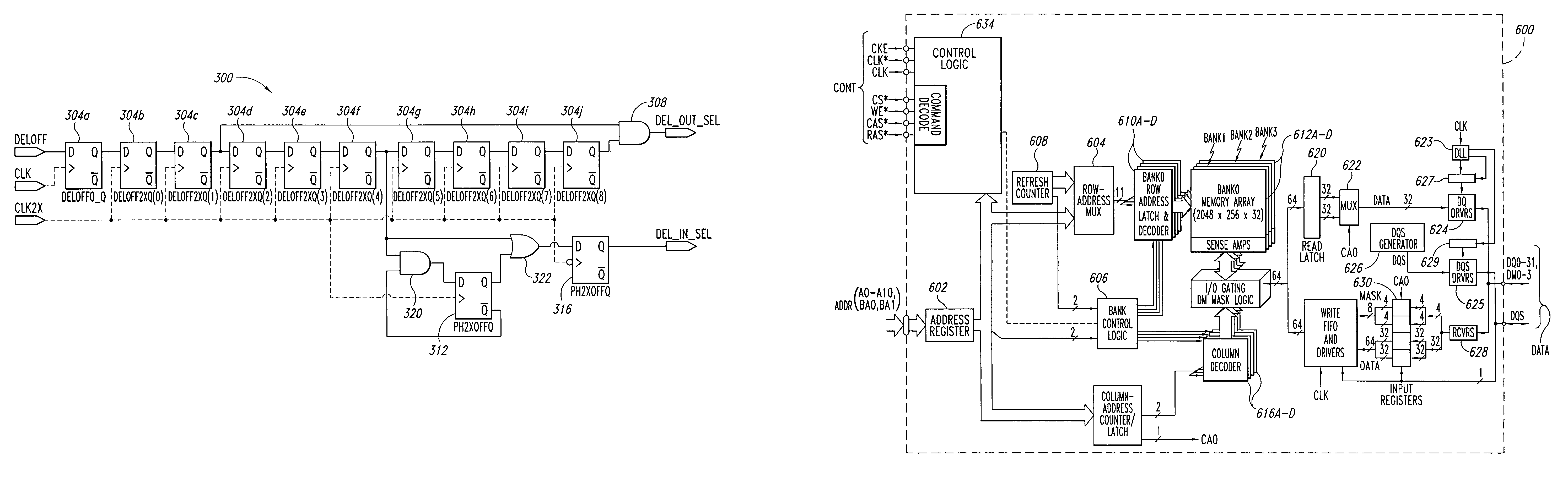
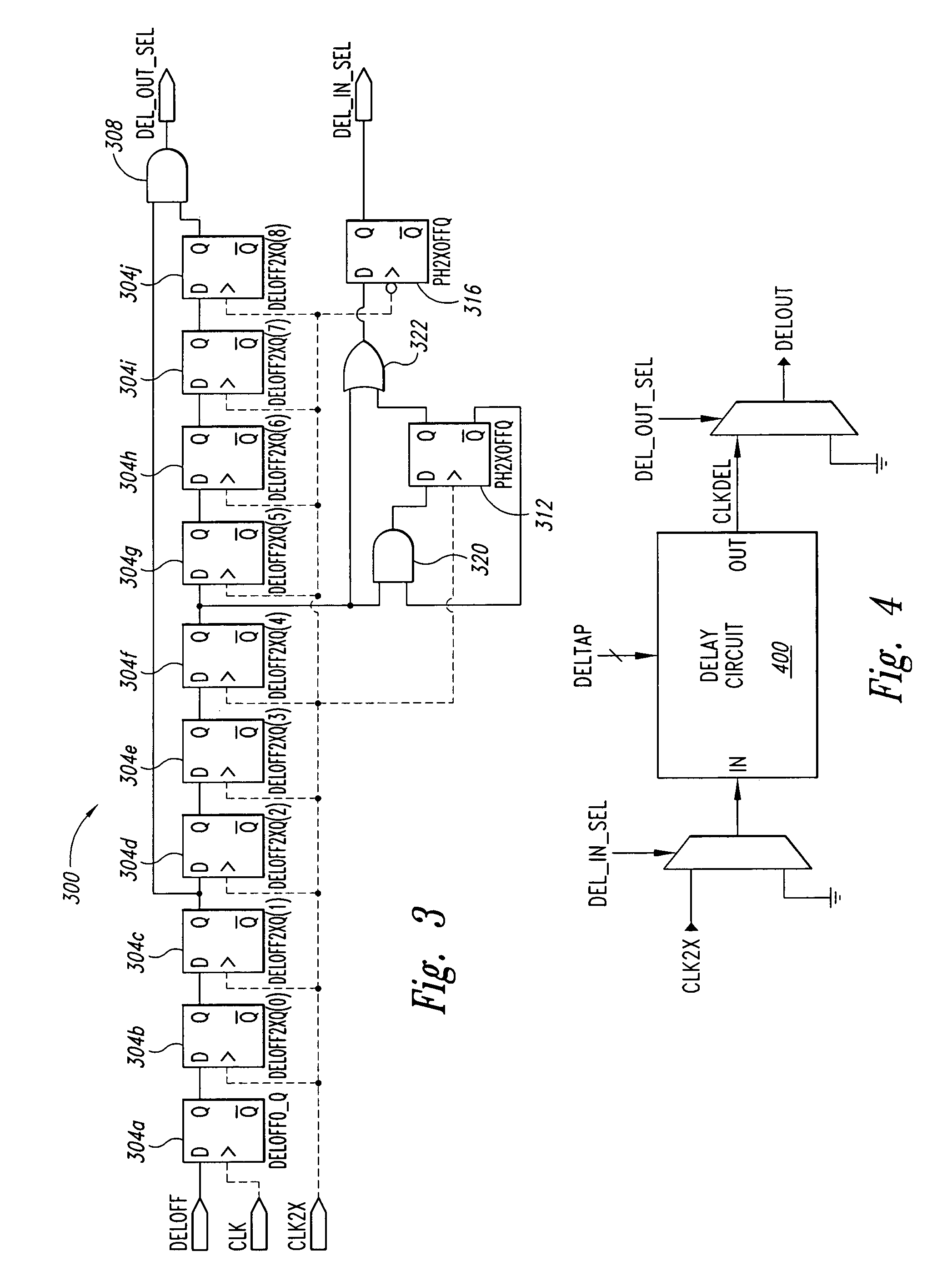
[0020]FIG. 3 illustrates a synchronizer circuit 300 according to an embodiment of the present invention. As will be described in greater detail below, the synchronizer circuit 300 can be used with a conventional adjustable delay circuit to preserve a pseudo-synchronous phase relationship between clock signals of different clock domains when the time delay of the adjustable delay circuit from which one of the clock signals is output is changed. Certain details are set forth below to provide a sufficient understanding of the invention. However, it will be clear to one skilled in the art that the invention may be practiced without these particular details. In other instances, well-known circuits, control signals, and timing protocols have not been shown in detail in order to avoid unnecessarily obscuring the invention.

[0021]The synchronizer circuit 300 includes a plurality of series connected positive edge triggered D flip-flops 304a–j. The first flip-flop 304a is coupled to receive a ...


PUM


Abstract

A synchronizer system and method that can be used with a conventional adjustable delay circuit to preserve a pseudo-synchronous phase relationship between clock signals of different clock domains when the time delay of the adjustable delay circuit from which one of the clock signals is output is changed.

Description

TECHNICAL FIELD[0001]This invention relates generally to generating clock signals, and more specifically, to a synchronizing circuit that can be used for maintaining a pseudo-synchronous phase relationship for clock signals of different time domains.BACKGROUND OF THE INVENTION[0002]Internal clock signals for a memory device are typically derived from a core system clock. The core system clock signal generally has a lower frequency than is desirable for internal clock signals, and consequently, higher frequency clock signals are generated from the core system signal for use as internal clock signals. The higher frequency clock signals generally have a frequency that is a multiple of the frequency of the core clock signal. For example, it is not unusual for internal clock signals to have a clock frequency that is two, three, or four times the core clock signal frequency. Techniques for generating clock signals having higher frequencies from the core clock signal are well known. Genera...

Claims


Application Information

Patent Timeline
Patent Type & Authority Patents(United States)
IPC IPC(8): G06F1/04G06F1/12H03K3/00
CPCG06F1/12H03K5/14G06F1/04
Inventor LABERGE, PAUL A.
Owner ROUND ROCK RES LLC
Why Eureka
Try Eureka