Image forming apparatus and holding method of image carrier

a technology of image carrier and holding method, which is applied in the direction of electrographic process apparatus, instruments, optics, etc., can solve the problems of image disturbance, color shift, or color deviation, contact (abutting) problem with respect to image carrier such as a photosensitive drum may similarly occur, and achieve the effect of suppressing image disturban

Inactive Publication Date: 2005-12-27
FUJIFILM BUSINESS INNOVATION CORP
View PDF10 Cites 8 Cited by
  • Summary
  • Abstract
  • Description
  • Claims
  • Application Information

AI Technical Summary

Benefits of technology

[0011]The present invention has been made to solve the above-explained technical problems, and therefore, has an object to provide an image forming apparatus capable of suppressing image disturbances produced when images are formed with employment of an image carrier, while a member abutting with respect to this image carrier is positively utilized.

Problems solved by technology

However, even in such a case that, for instance, a developing device for forming a single color image is employed in addition to such a tracking roller as described in the above-explained patent publication, when an abutting function is provided in which a predetermined member abuts against a photosensitive drum due to a predetermined positioning aspect, the following problem may occur.
That is, weight produced when these members abut against the photosensitive drum may cause such a problem with respect to this photosensitive drum.
This contact (abutting) problem with respect to an image carrier such as a photosensitive drum may similarly occur even in the case that a transfer apparatus such as a transfer belt which abuts against this image carrier is employed.
When these abutting members are strongly depressed with respect to the image carrier such as the photosensitive drum, there are some possibilities that the shaft of the photosensitive drum is bent due to the weight of these abutting members, and thus, this shaft bending phenomenon may cause disturbances of images, for instance, color shifts, or color deviation.
This bending phenomenon may give an adverse influence to holding characteristics of the photosensitive drum, and further, this weight may give an adverse influence to such a phenomenon that the shaft of the photosensitive drum is bent in accordance with a time elapse.
This problem may be conspicuously emphasized in such a case that a diameter of a drum shaft is made narrower due to a cost-down reason and / or light weight of an image forming apparatus.
More specifically, in the case that such a drum holding structure that one shaft is penetrated is not employed, but a photosensitive drum is supported by two shafts (namely, cantilever shafts) which are projected from both ends of this photosensitive drum in a half way, since these cantilevers own deteriorated stabilities, abutting weight given to the photosensitive drum may readily give an adverse influence to a holding characteristic of this photosensitive drum by this shaft.
Also, for instance, as in a rotary type developing apparatus, in the case that a member abuts against an image carrier (e.g., photosensitive drum and photosensitive belt) at predetermined timing, when this member is advanced (abuts) and is retracted (separated) to / from this image carrier, shocks and vibrations may occur.
These shocks and vibrations are transferred to, for example, a primary transferring unit, a secondary transferring unit, and an exposing unit, so that disturbances of images may readily occur.
However, for example, in the case that a diameter of a photosensitive drum is decreased, or a length of a photosensitive belt is shortened, and thus, respective apparatuses capable of performing respective image forming processes are arranged in the vicinity of these apparatuses, for instance, even when upset exposing timing, transferring timing cannot be displaced.
As a result, as to shocks and vibrations caused by abutting operation of members, disturbances of images could not sufficiently suppressed in these conventional image forming apparatuses

Method used


Image

  • Image forming apparatus and holding method of image carrier
  • Image forming apparatus and holding method of image carrier
  • Image forming apparatus and holding method of image carrier

Examples


Embodiment Construction

[0031]Referring now to attached drawings, various embodiment modes of the present invention will be described.

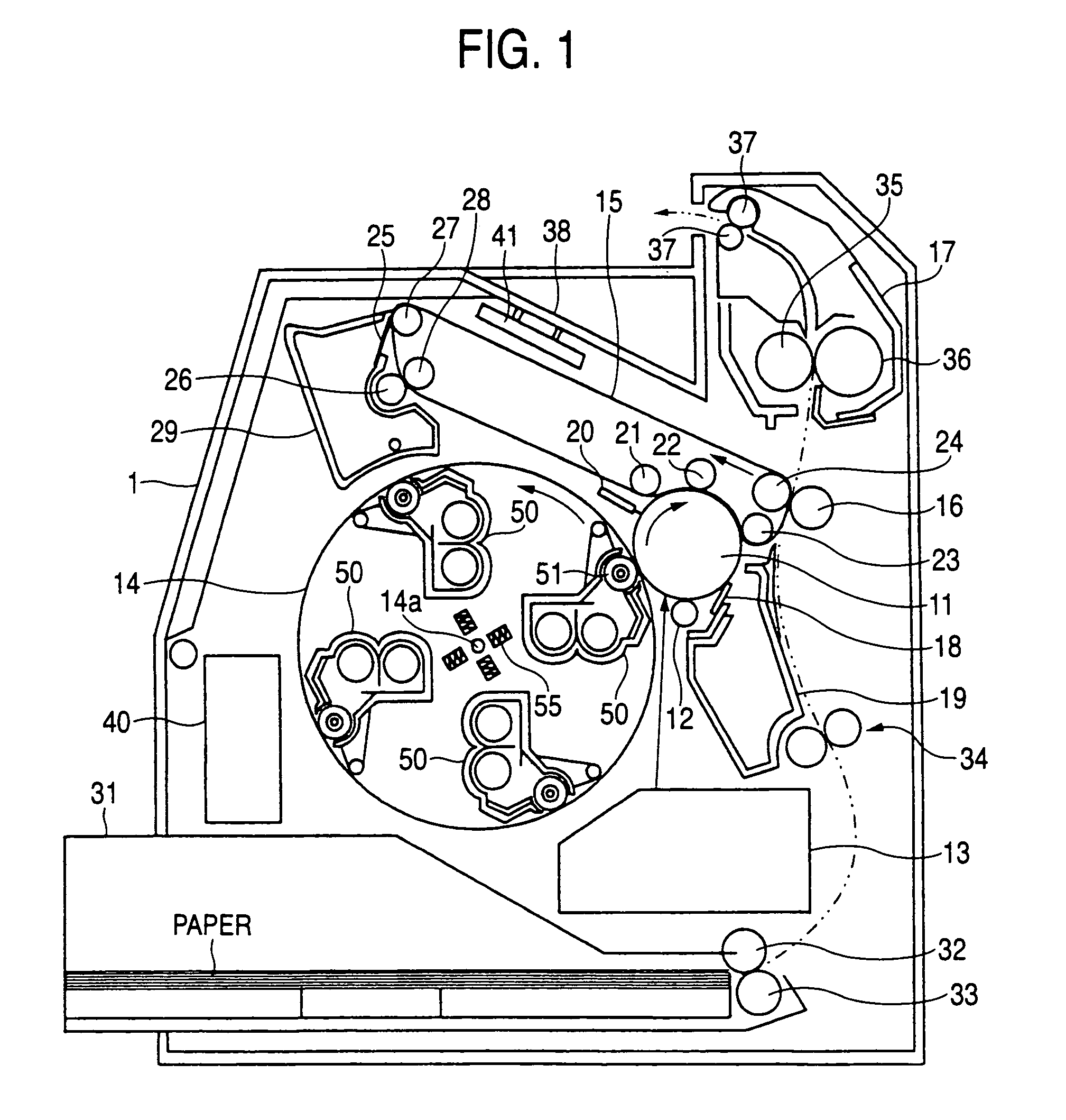
[0032]FIG. 1 is a diagram for indicating an entire structure of an image forming apparatus to which an embodiment mode of the present invention may be applied. This drawing shows a digital color printer with employment of a rotary type developing apparatus. In the image forming apparatus shown in FIG. 1, a main body 1 of this image forming apparatus is provided with a photosensitive drum 11, a charging device 12, an exposing apparatus 13, and a developing apparatus 14. The photosensitive drum 11 corresponds to an image carrier which forms an electrostatic latent image to carry thereon a toner image. The charging device 12 applies electron charges to the photosensitive drum 11 so as to charge this photosensitive drum 11 by employing a charge roller and the like. The exposing apparatus 13 is operated in such a manner that the charged photosensitive drum 11 is exposed in an exp...


PUM


Abstract

An image forming apparatus is included of a pivotally rotated photosensitive drum, a developing roller for developing an electrostatic latent image formed on this photosensitive drum, and an intermediate transfer belt for temporarily holding the toner image which has been developed to be formed by the developing roller. This developing roller is equipped with a tracking roller which abuts against the photosensitive drum so as to keep a distance between the developing roller and the photosensitive drum as a constant distance. A direction of weight “a” produced by this tracking roller with respect to the photosensitive drum may be positioned within a so-called “wrap range” corresponding to an abutting range between the intermediate transfer belt and the photosensitive drum.

Description

CROSS REFERENCE OF RELATED APPLICATION[0001]This application is based on and claims priority under 35 U.S.C. § 119 with respect to Japanese Patent Application No. 2002-364484 filed on Dec. 16, 2002, the entire content of which is incorporated herein by reference.BACKGROUND OF THE INVENTION[0002]1. Field of the Invention[0003]The present invention relates to image forming apparatus such as printers, copying machines, and facsimile apparatus. More specifically, the present invention is directed to image forming apparatus equipped with a member for abutting against image carriers.[0004]2. Description of the Related Art[0005]In image forming apparatus using an electrophotographic system such as printers, copying machines, and facsimile apparatus, image forming operations are carried out as follows. That is, after latent images are acquired by latent image forming unit in such a manner that light is irradiated onto image carriers such as photosensitive drums which have been uniformly cha...

Claims


Application Information

Patent Timeline
Patent Type & Authority Patents(United States)
IPC IPC(8): G03G15/01G03G15/08G03G15/16
CPCG03G15/0131G03G15/0813G03G2215/0177
Inventor OKAMOTO, MASAYASASAKI, KEIJI
Owner FUJIFILM BUSINESS INNOVATION CORP
Why Eureka
Try Eureka