Laterally ejecting fluid flow control system and method

a fluid flow control and lateral ejection technology, applied in the field of systems and methods for controlling fluid flow, can solve the problems of effectively mixing liquid feed, vertical splashing from the bottom of the cup,

Inactive Publication Date: 2006-01-03
WELBOURNE INNOVATIONS
View PDF34 Cites 16 Cited by
  • Summary
  • Abstract
  • Description
  • Claims
  • Application Information

AI Technical Summary

Benefits of technology

[0082]prevents liquid feed, (eg. milk), from being sprayed upward and not becoming contained in an associated cup, or being sprayed into the face of a piglet when the cup is relatively empty, which action can waste liquid feed and even scare young piglets away from the liquid feeder system;
[0083]provides means to prevent piglets from “playfully” over-activating a “spray” causing liquid feeder system to the point that liquid feed is wastefully ejected beyond the cup, or fills and then wastefully overflow-spills from the cup;
[0085]provides means for preventing liquid feed in a cup from flowing back into the source thereof and contaminate source liquid feed if pressure is source lost, which pressure is maintained at below 30 psi and is preferably between 10–20 psi; and
[0086]provides means for utilizing higher than 10–20 psi without overfilling a cup.

Problems solved by technology

A perceived problem with this system is that if water is ejected at high pressure it can bounce from the bottom of the cup and splash vertically out of the cup.
Further, it is noted that the 210 system is designed for use by poultry, which tend not to effectively mix liquid feed as they feed.

Method used


Image

  • Laterally ejecting fluid flow control system and method
  • Laterally ejecting fluid flow control system and method
  • Laterally ejecting fluid flow control system and method

Examples


Embodiment Construction

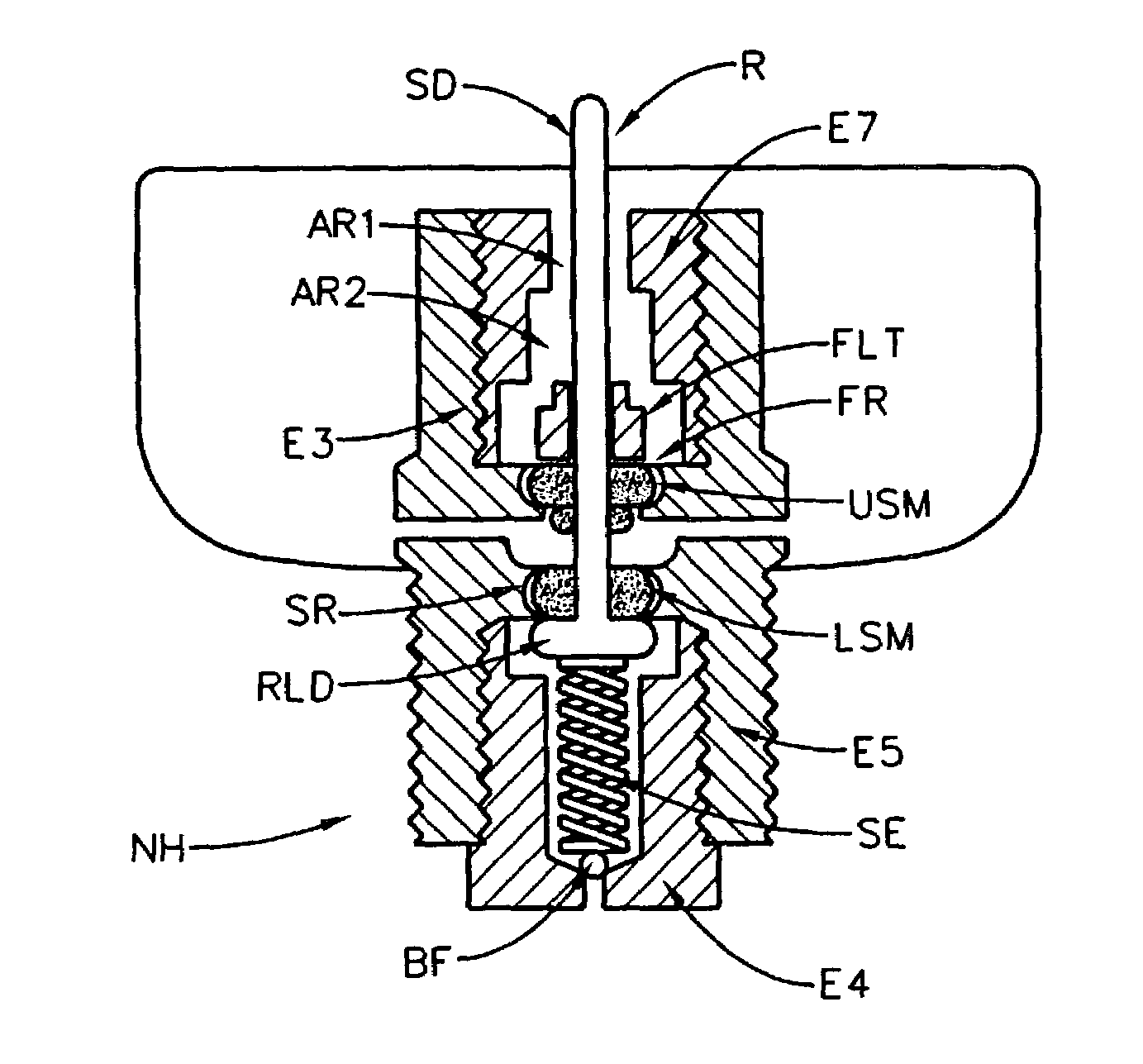
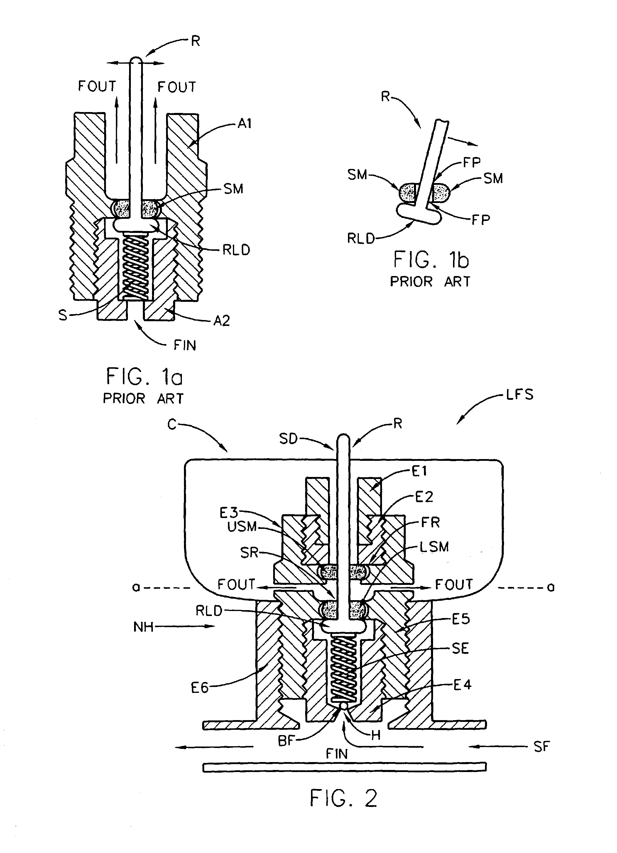
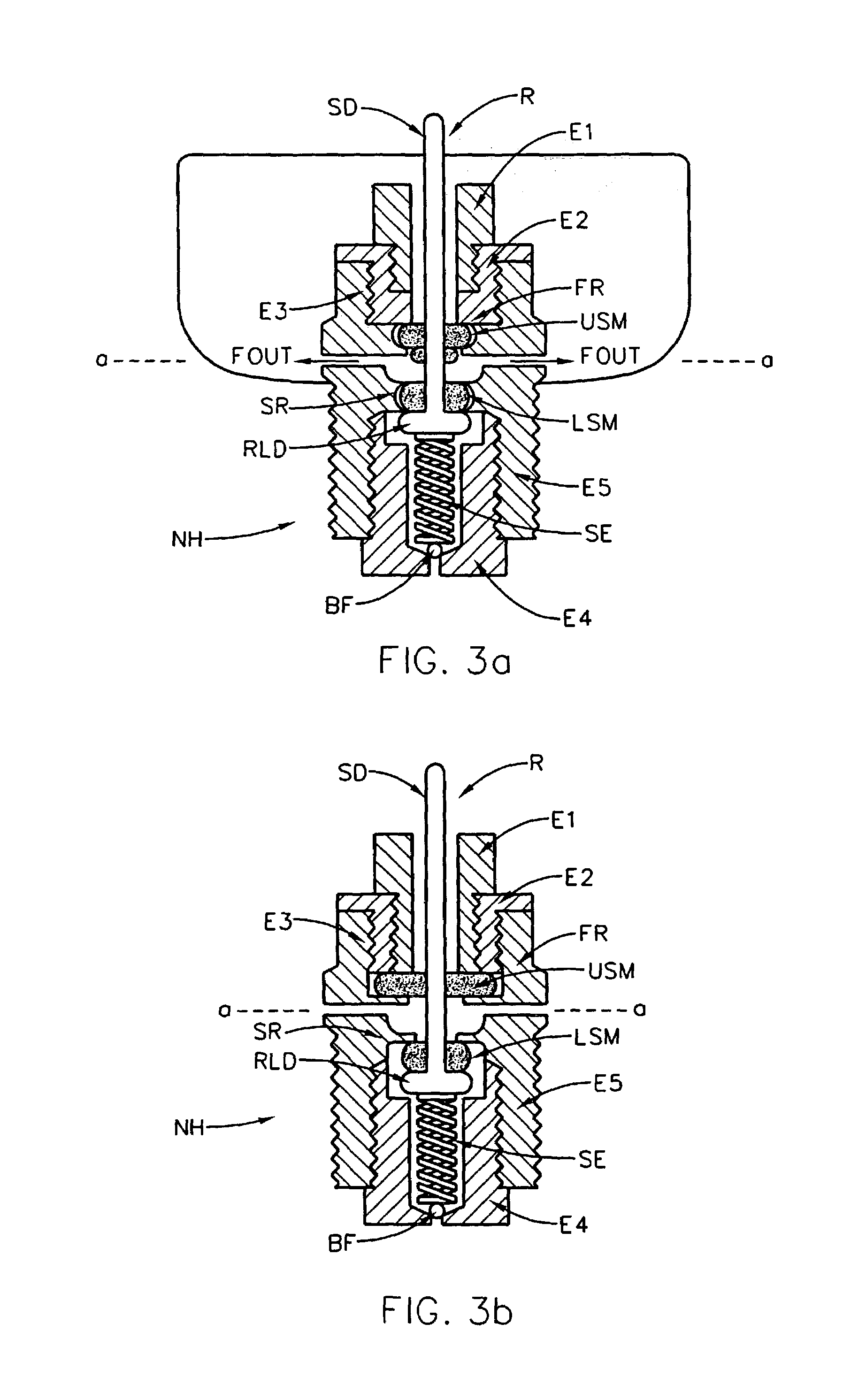
[0096]Turning now to FIG. 1a, there is shown a typical Prior Art Fluid Feeder System. Shown are basic structural elements (A1) and (A2), and a Rod means (R) with a Substantially Abrupt Larger Diameter near its lower aspect (RLD). Also shown are a Seal Means (SM), and a Spring (S) (shown as a coil in FIG. 1a, but it is also known to use a functionally similar pliable soft mass of material), to maintain fluid sealing contact between the Substantially Abrupt Larger Diameter portion of the Rod means (R) and the Seal Means (SM). In use, when the Rod means (R) is positioned to project substantially vertically as shown, no fluid can pass from the Input (FIN) as Output (FOUT). However, when the Rod means (R) is caused to move off the shown vertical orientation, (eg. see arrows pointing to the Right or Left in FIG. 1a), as shown in FIG. 1b, the Seal Means (SM) allows fluid to pass through the Flow Path (FP), (see FIG. 1b), from input (FIN), through said Seal Means (SM), and eject substantial...


PUM


Abstract

A system for accepting fluid from a source supply, then ejecting it along a substantially non-radial laterally oriented locus such that the fluid enters a cup with a mixing effect but with only minimal splashing, typically including a restriction element frame which substantially bisects the cup serves to control access thereto and a float based automatic flow restricting element; and methodology for its use in the liquid feeding of animals such as piglets.

Description

[0001]This Application is a CIP of application Ser. No. 10 / 128,223 Filed Apr. 24, 2002, now abandoned and claims benefit of Provisional Applications No. 60 / 341,780, filed Dec. 17, 2001 and No. 60 / 404,001 Filed Aug. 17, 2002.TECHNICAL FIELD[0002]The disclosed invention relates to systems and methods for controlling fluid flow, and more particularly to a system comprising means for accepting fluid from a source supply, then ejecting said fluid along a non-radial laterally oriented locus substantially without any upward or downward orientation such that said fluid enters a cup with a mixing effect, but with only minimal splashing out thereof. Preferably a restriction element frame substantially bisects the cup as viewed from above and serves to control access to flow ejection control rod means which project in a plane defined thereby, and an automatic fluid ejection limiting float element control further distinguish the disclosed system. The disclosed system finds application in a meth...

Claims


Application Information

Patent Timeline
Patent Type & Authority Patents(United States)
IPC IPC(8): A01K7/04A01K7/06
CPCA01K39/0213A01K7/06
Inventor WELBOURNE, STEPHEN B.
Owner WELBOURNE INNOVATIONS
Why Eureka
Try Eureka