Vortex cooling of turbine blades

a turbine blade and vortex cooling technology, which is applied in the direction of propulsive elements of rotary type, machines/engines, engine manufacture, etc., can solve the problems of low convective cooling effectiveness, difficult control of radial and chord-wise cooling flow, and the cooling construction approach has its downsides

Inactive Publication Date: 2006-01-03
FLORIDA TURBINE TECH
View PDF2 Cites 77 Cited by
  • Summary
  • Abstract
  • Description
  • Claims
  • Application Information

AI Technical Summary

Problems solved by technology

While this patent discloses a near wall cooling technique, this cooling construction approach has its downside because the hot gas temperature and pressure variation of the engine's working medium makes the control of the radial and chord-wise cooling flow difficult to achieve.
A single pass radial channel flow as taught by the U.S. Pat. No. 5,720,431, supra, is not the ideal method of utilizing cooling air and as a consequence, this method results in a low convective cooling effectiveness.
As will be appreciated by those familiar with this technology, film cooling on the suction side downstream of the gage point, i.e., the point where the two adjacent blades define the throat of the passage between blades, adversely affects the aerodynamics of film mixing and hence is a deficit in performance.

Method used


Image

  • Vortex cooling of turbine blades
  • Vortex cooling of turbine blades
  • Vortex cooling of turbine blades

Examples


Embodiment Construction

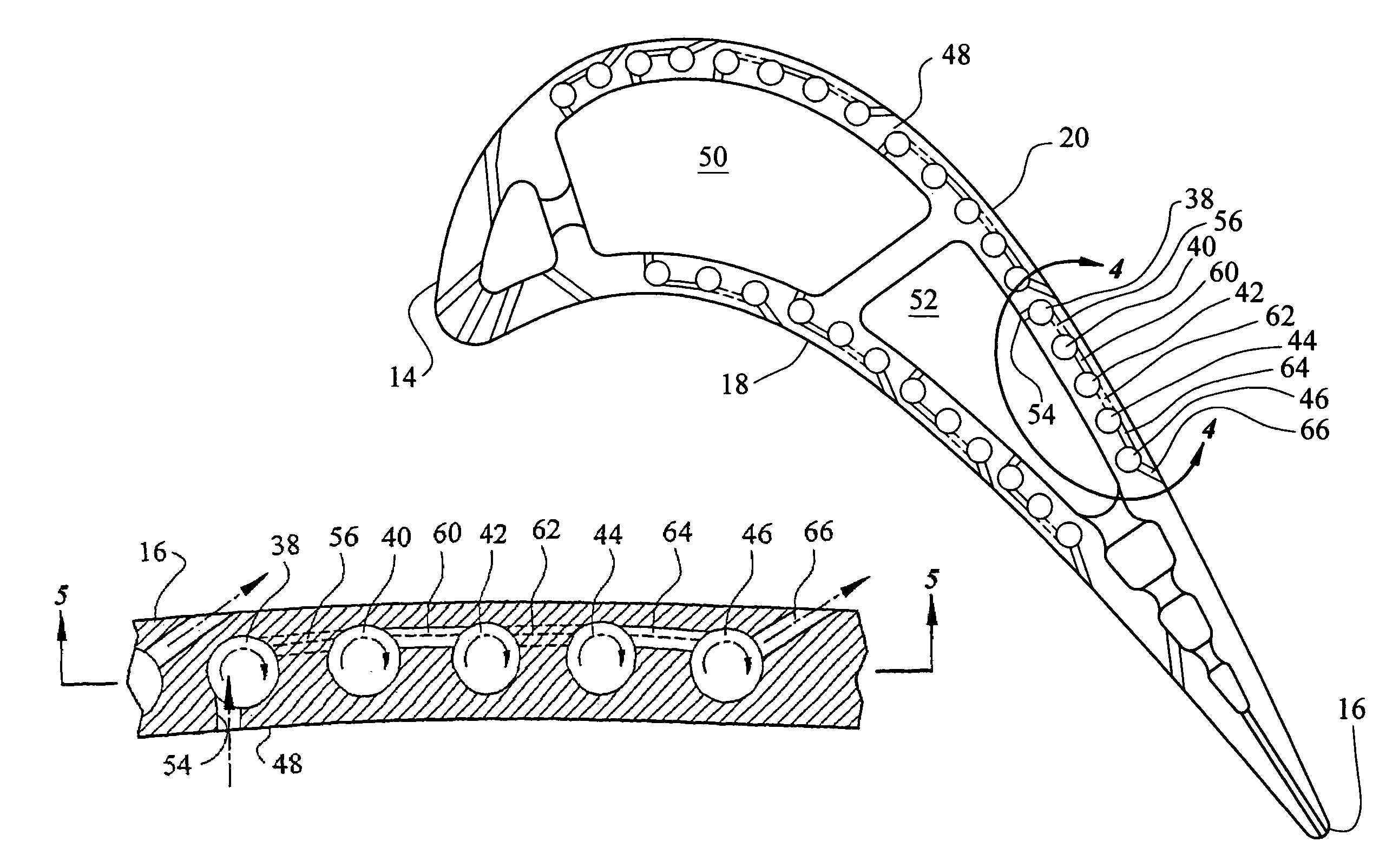
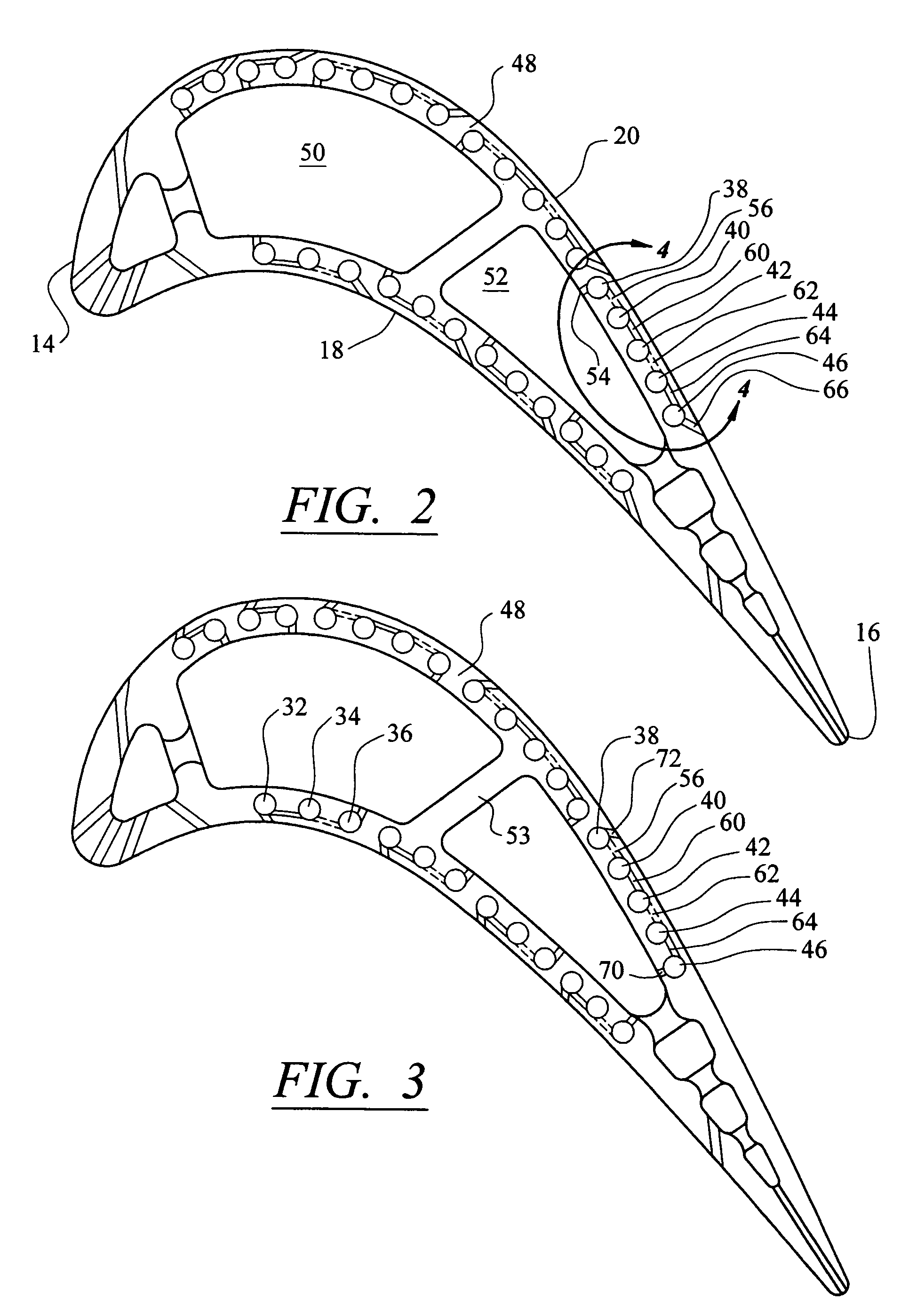
[0025]While this invention is being described showing a particular configured turbine blade as being the preferred embodiment, as one skilled in this art will appreciate, the principals of this invention can be applied to any other turbine blade that requires internal cooling and could be applied to vanes as well. Moreover, the number of cells and their particular shape and location can be varied depending on the particular specification of the turbine operating conditions. The leading edge and trailing edge cooling configuration and technique are not apart of this invention and any well known techniques could also be utilized and as mentioned earlier the technique described in U.S. patent application Ser. No. 10 / 791,581 could equally be utilized.

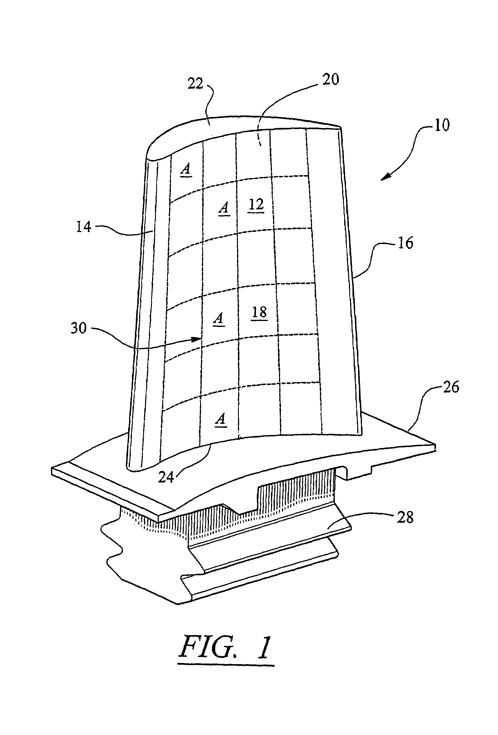
[0026]A better understanding of this invention can be had by referring to FIGS. 1 through 5 which illustrate a turbine blade generally indicated by reference numeral 10 (FIG. 1) comprising the airfoil 12 having a leading edge 14, a trailing...


PUM


Abstract

A near wall cooling technique for cooling the pressure and suction sides of a turbine airfoil that includes a matrix of cells oriented chord-wise and extending longitudinally having vortex chambers with vortex creating passages feeding coolant from interior of the blade to each of the cells, interconnecting passageways interconnecting each of the vortex chambers and discharge film cooling passageway discharging coolant adjacent the outer surface of the pressure and suction sides. The alternate passageways are staggered and each are tangentially oriented to introduce a swirling motion in the coolant as it enters each of the vortex chambers. The cells may be oriented to be in a staggered or in an in-line array and the number of cells, the number of vortex chambers and the dimension of the cells, vortex chambers and passageways are selected to match the heat load and the temperature requirements of the material of the blade. The direction of flow within each cell is selected by the designer. The aft portion may be internally cooled before discharging the coolant as a film upstream of the gage point to avoid aerodynamic losses associated with film mixing.

Description

[0001]This application claims benefit of a prior filed U.S. provisional application Ser. No. 60 / 454,120, filed on Mar. 12, 2003, entitled “NEAR WALL MULTI-VORTEX COOLING CONCEPT” by George Liang.CROSS-REFERENCE TO RELATED APPLICATION[0002]This patent application relates to U.S. pat. application Ser. No. 10 / 791,581 inasmuch as both inventions relate to cooled turbine blades and both inventions can be utilized together and is incorporated herein by reference.TECHNICAL FIELD[0003]This invention relates to air cooled turbines for gas turbine engines and particularly to cooling of the pressure and suction surfaces of the turbine blade with coolant air that has imparted thereto vortices.BACKGROUND OF THE INVENTION[0004]As is well known in the gas turbine engine technology, the efficiency of the engine is greatly enhanced by increasing the temperature of the turbine and / or reducing the amount of air that is required to maintain the turbine components within their tolerable limits. In other...

Claims


Application Information

Patent Timeline
Patent Type & Authority Patents(United States)
IPC IPC(8): F01D5/18B63H1/14
CPCF01D5/186F01D5/187F05D2260/202F05D2260/201F05D2250/231
Inventor LIANG, GEORGE
Owner FLORIDA TURBINE TECH
Why Eureka
Try Eureka