Terminal device of electrical apparatus

a terminal device and electrical equipment technology, applied in the direction of switch terminal/connection, coupling device connection, relay, etc., can solve the problem that the frame of the box terminal device cannot be used for the terminal device of the press terminal, and achieve the effect of reducing the manufacturing cost of the frame, facilitating cable connection system change, and simple inventory control

Active Publication Date: 2006-01-03
FUJI ELECTRIC FA COMPONENTS & SYST CO LTD
View PDF11 Cites 6 Cited by
  • Summary
  • Abstract
  • Description
  • Claims
  • Application Information

AI Technical Summary

Benefits of technology

[0012]In order to attain the objects described above, according to a present invention, a terminal device of electrical apparatus includes a frame capable of receiving at least one conventional terminal strip having a box-shaped terminal fitting. The frame has at least two insulation walls provided in parallel with each other, each having a groove formed in the horizontal direction; a bottom plate made of an insulation material provided between the at least two insulation wails; and a wall standing from the bottom plate. The two adjacent insulation walls, the bottom plate, and the wall form a box-like space for holding the box-shaped terminal fitting. The terminal strip having a box-shaped terminal fitting is inserted into the grooves formed in the insulation walls, and the box-shaped terminal fitting is held in the box-like space with the terminal strip secured to the frame for preventing slip off.
[0013]According to the present invention, the terminal device of an electrical apparatus further includes at least one terminal strip having a terminal screw for a press terminal; and at least one attachment piece made of an insulation material and having a cylinder-like recess on an upper face and a projection on a lower face. The attachment piece has a size of being fitted in the box-like space. The bottom plate has a recess for engaging the projection on the lower face of the attachment piece. In a state that the terminal strip having a box-shaped terminal fitting is removed, the attachment piece is inserted in the box-like space, so that the projection on the lower face of the attachment piece is fitted to the recess formed in the bottom plate. The terminal strip having a terminal screw for a press terminal is inserted in the grooves formed in the insulation walls, so that a screw section of the terminal screw is fitted into the cylinder-like recess in the upper face of the attachment piece for preventing the terminal strip from slipping off and the terminal strip is attached to the attachment piece.
[0017]According to the invention, it is possible to use the common single frame for the box terminal device and the terminal device for a press terminal, thereby making it easy to change a cable connection system after an electrical apparatus is installed. It is also possible to reduce manufacturing cost of the frame and make inventory control simple.

Problems solved by technology

Therefore, for example, the frame for the box terminal device can not be used for the terminal device for the press terminal.

Method used


Image

  • Terminal device of electrical apparatus
  • Terminal device of electrical apparatus
  • Terminal device of electrical apparatus

Examples


Embodiment Construction

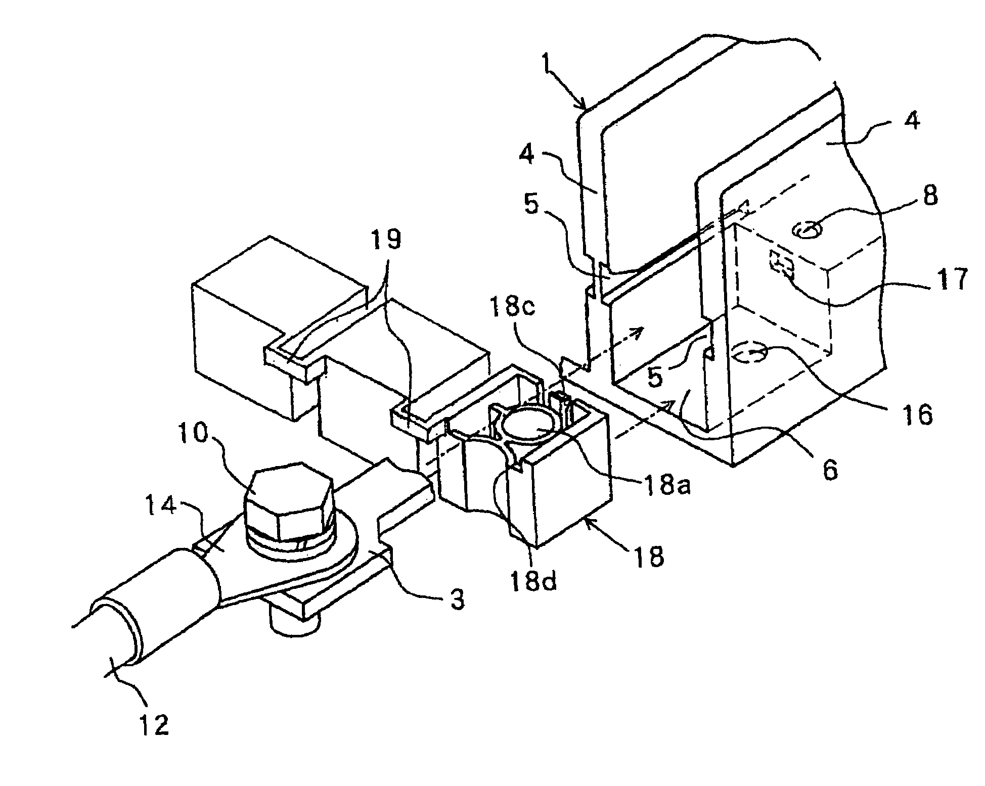
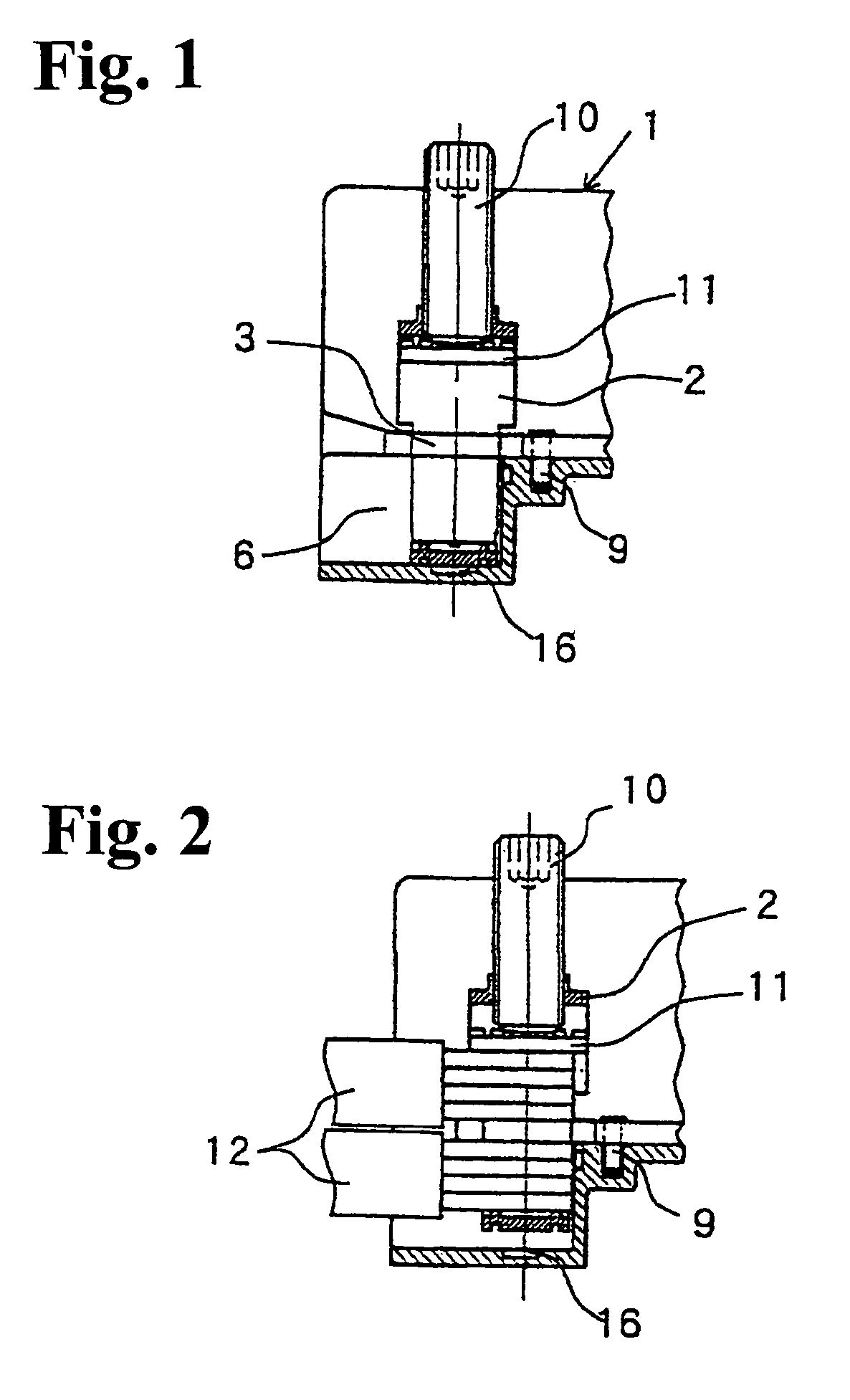
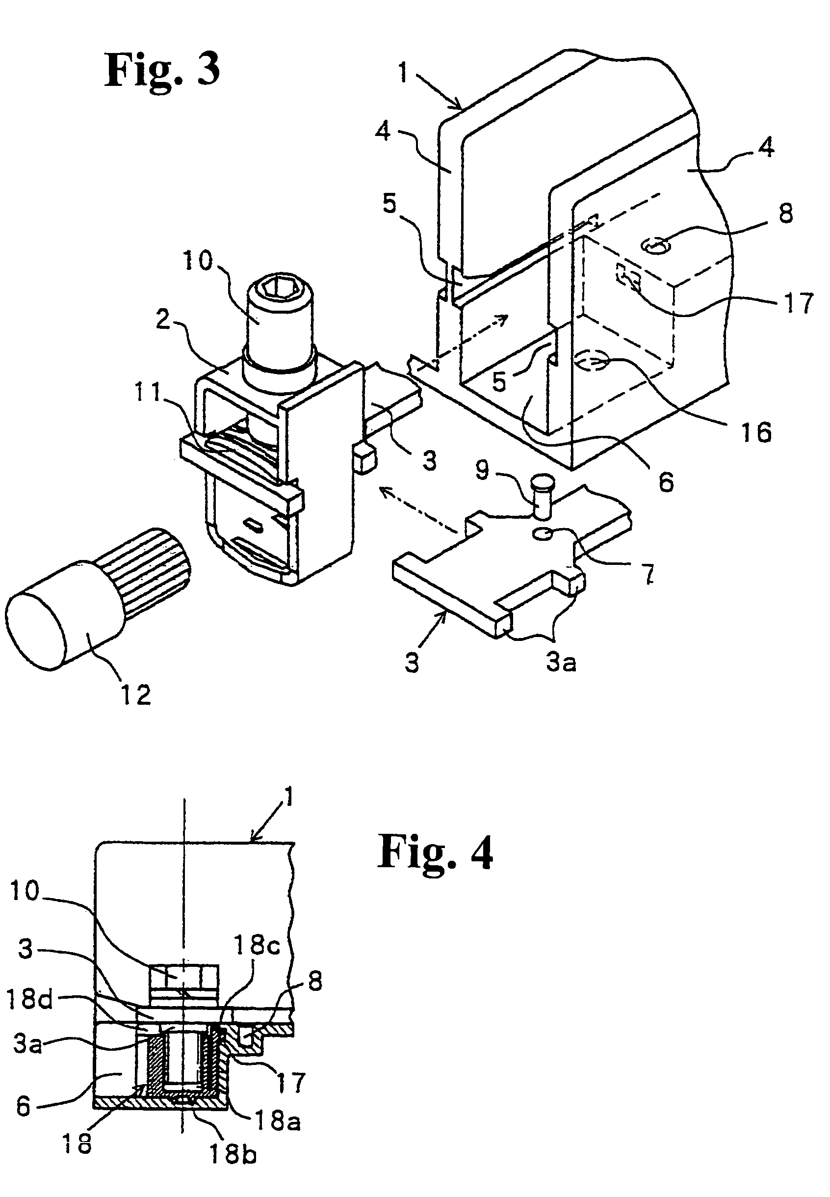
[0030]Hereunder, embodiments of the present invention will be explained with reference to FIG. 1 to FIG. 6. The parts corresponding to those in the conventional devices are designated by the same reference numerals and signs. FIG. 1 to FIG. 3 show a terminal device provided as a box terminal device according to an embodiment of the invention. FIG. 1 is a vertical cross sectional view showing a structure of the box terminal device, FIG. 2 is a vertical cross sectional view showing the box terminal device in FIG. 1 in a state in which a cable is connected thereto, and FIG. 3 is an exploded perspective view showing the box terminal device in FIG. 1.

[0031]In FIG. 1 to FIG. 3, differences from the conventional device in FIG. 7 to FIG. 9 are that a bottom plate of a frame 1 forming a box-like space 6 has a cylinder-like shallow recess 16, and a wall standing from the bottom plate and forming the box-like space 6 has a rectangular shallow recess 17 (see FIG. 3). Structures of a terminal fi...


PUM


Abstract

A terminal device of an electrical apparatus includes a frame, at least one attachment piece and at least one terminal strip with a terminal screw, The frame includes at least two side walls with grooves, a bottom wall disposed between the at least two side walls and having a first recess, and a rear wall standing from the bottom wall to form a box-shaped space. The attachment piece is fitted into the box-shaped space, and has a cylinder-shaped recess and a lower surface with a projection for engaging the first recess. The terminal strip is inserted into the box-shaped space along the grooves so that the terminal screw is fitted into the cylinder-shaped recess for attaching the terminal strip to the attachment piece.

Description

BACKGROUND OF THE INVENTION AND RELATED ART STATEMENT[0001]The present invention relates to a terminal device provided in an electrical apparatus such as an electromagnetic contactor, a molded-case circuit breaker, and a terminal base.[0002]A terminal device includes a box terminal device with a box fitting for directly connecting an end of a cable, and a terminal device for connecting a cable with a press terminal at an end thereof. Japanese Patent Publication (Kokai) No. 2002-190331 has disclosed a conventional box terminal device.[0003]FIG. 7 to FIG. 9 show a structure of the conventional box terminal device provided in an electromagnetic contactor. FIG. 7 is a vertical cross sectional view showing the box terminal device, FIG. 8 is a vertical cross sectional view showing the box terminal device in FIG. 7 in a state in which a cable is connected thereto, and FIG. 9 is an exploded perspective view showing the box terminal device in FIG. 7. In FIG. 7 to FIG. 9, particularly in FIG....

Claims


Application Information

Patent Timeline
Patent Type & Authority Patents(United States)
IPC IPC(8): H01R4/36H01R4/38H01H1/58H01H50/14H01H71/08H01H73/20H01R4/34H01R9/18H01R11/12
CPCH01R4/363H01R4/34H01H2001/5861H01H2011/0037H01R11/12H01R9/22H01R13/514
Inventor TAKAYA, KOUETSU
Owner FUJI ELECTRIC FA COMPONENTS & SYST CO LTD
Why Eureka
Try Eureka