Electrical heater apparatus

a technology for electric heaters and heaters, applied in electrical appliances, ohmic-resistance heating, ohmic-resistance heating details, etc., can solve the problems of labor-intensive installation procedures and cumbersomeness, and achieve the effect of reliable, long-lasting, and easy and inexpensive installation

Inactive Publication Date: 2006-01-03
SENSATA TECH MASSACHUSETTS INC
View PDF8 Cites 10 Cited by
  • Summary
  • Abstract
  • Description
  • Claims
  • Application Information

AI Technical Summary

Benefits of technology

[0006]It is therefore an object of the invention to provide a reliable, long lasting and inexpensive heating device for crankcase heaters and the like which are more easily and inexpensively installed in a heater well of a compressor than prior art heaters.
[0008]Yet another object of the invention is the provision of a crankcase heater which overcomes the limitations of the prior art noted above and provides a more cost effective solution.

Problems solved by technology

However, due to tolerance stack-ups between the device and the inner well diameter, the ceramic body is required to be undersized so that it will fit into the metal well attached to the compressor housing.
Although the above described heater device is reliable, long lasting and inexpensive, the installation procedure is more labor intensive and cumbersome than desired.

Method used


Image

  • Electrical heater apparatus
  • Electrical heater apparatus
  • Electrical heater apparatus

Examples


Embodiment Construction

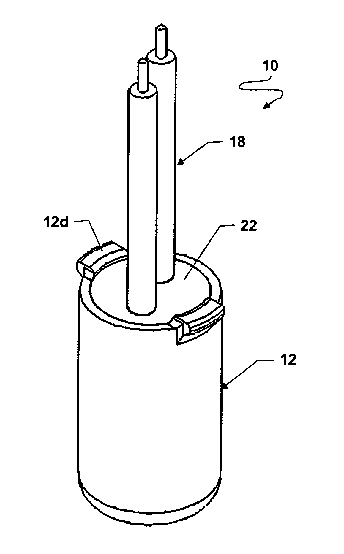
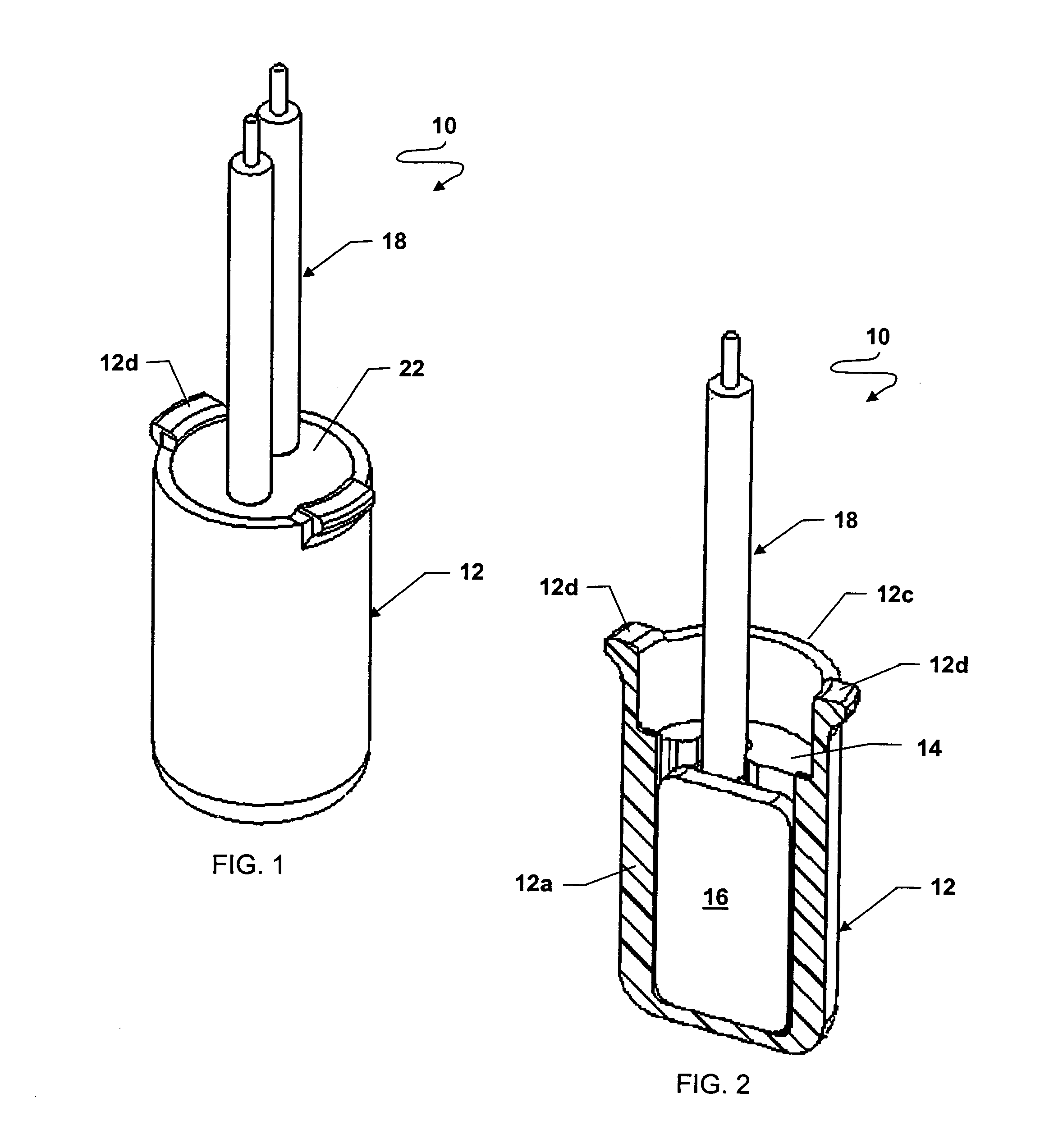
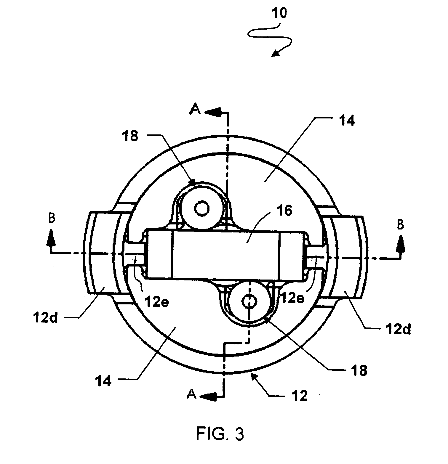
[0022]With particular reference to FIGS. 1–6, numeral 10 indicates a heater device made in accordance with the preferred embodiment of the present invention. Heater device 10 comprises a tubular, generally cylindrical casing 12 formed of relatively flexible, electrically insulative and thermally conductive material such as silicone elastomer. Casing 12 has an elongated side wall 12a, a bottom end wall 12b and an open end 12c. Diametrically opposed retainer projections 12d are integrally formed at open end 12c and will be discussed below.

[0023]A heater assembly comprising first and second like terminal blocks 14 sandwiching an electrical resistance heating element 16 with electrical lead wires and spring contacts 18 are closely received in the casing in good thermal conductive relationship therewith.

[0024]With particular reference to FIG. 6, each terminal block 14 is a generally semi-cylindrical solid of suitable heat conductive material, such as aluminum. The length of terminal bloc...


PUM


Abstract

A self retaining crankcase heater (10) has a tubular casing (12) of relatively flexible, thermally conductive material in which is received a PTC element (16), sandwiched by semi-cylindrical terminal blocks (14). Spring contacts (18a) are received in grooves (14c) of the terminal blocks and the assembly is potted with heat conductive material (20) and sealed with sealant (22). Locking projections (12d) are formed at open end (12c) of the casing which are lockingly received in an annular recess (24a; 26d) of a well (24; 26) in a compressor housing wall.

Description

FIELD OF THE INVENTION[0001]This invention relates generally to electrical heaters and more particularly to electrical heaters for crankcase heaters used in compressor heat pump applications.BACKGROUND OF THE INVENTION[0002]Crankcase heaters are typically used in HVAC compressor applications. After prolonged off periods and before start up, refrigerant in compressors tend to mix with oil in the compressor forming a refrigerant / oil solution. A crankcase heater is used to drive out refrigerant from the refrigerant / oil solution in order to prevent damage to the compressor due to lack of lubrication and / or high solution volumes.[0003]An effective crankcase heater which has become widely used is shown and described in U.S. Pat. No. 4,236,065. This heater device comprises a self-regulating positive temperature coefficient of resistivity (PTC) element potted inside a thermally conductive ceramic body, such as alumina or steatite. The ceramic body and PTC element are potted with grit (alumi...

Claims


Application Information

Patent Timeline
Patent Type & Authority Patents(United States)
IPC IPC(8): H05B3/10
CPCH05B3/06H05B3/44H05B2203/02
Inventor NGUON, BUNRATTHANNA
Owner SENSATA TECH MASSACHUSETTS INC
Why Eureka
Try Eureka