Water Filter Faucet And Cartridge Therefor

a filter faucet and cartridge technology, applied in the direction of filtration separation, separation process, treatment involving filtration, etc., can solve the problems of inconvenient installation and replacement of filter elements for users not mechanically inclined, complex and expensive water treatment devices of the prior art designed for use on or above the sink surface or countertop, and public water supplies contaminated with many undesirables, etc., to achieve reliable and long-lasting effects

Active Publication Date: 2013-07-04
LONIEWSKI GRZEGORZ +3
View PDF3 Cites 5 Cited by
  • Summary
  • Abstract
  • Description
  • Claims
  • Application Information

AI Technical Summary

Benefits of technology

[0016]It is a primary objective of the present invention to provide a reliable, long-lasting, and inexpensive water treatment assembly that corrects and overcomes the disadvantages and problems of the prior art.

Problems solved by technology

Water consumers are increasingly aware that public water supplies are contaminated with many undesirable chemicals and microorganisms capable of impairing the health of those who consume the water.
Water treatment devices of the prior art designed for use on or above the sink surface or countertop are mostly complex and expensive devices with requirements for installation and periodic filter element replacement being intimidating for those users not mechanically inclined.
Embodiments intended to reduce complexity have created sinktop nuisances involving faucet mounted filters, faucet mounted diverter valves with tubing, complex and costly bases with large footprints on the sink or countertop, and inefficient filter elements with short lifespans requiring relatively frequent replacement.
These filter devices require a complex watertight housing for the filter element wherein water flows in and around the filter.
The pressurized housings increase design requirements and manufacturing costs while also increasing the potential for leaks.
When not in use, water stagnates within the filter housing developing bacterial slime that accumulates over time.
This bacterial slime decreases the lifespan of the filter while simultaneously mixing with the treated water that is consumed.
The bacterial slime accumulation requiring cleaning and water spillage associated with filter element replacement makes the task unpleasant and often unintentionally serves to discourage filter replacement, further leading to postponing the task, resulting in increased bacterial growth and consumption.
This water treatment device suggests a custom base that is complicated in design and requires a custom filter.
This large outer diameter of the base consumes a significant amount of material and countertop space.
Thereby creating manufacturing inefficiencies in the form of expensive tooling and machining time, and increasing the potential for water leakage through the engaged threads.
Similarly, the custom filter outflow port suggests an inefficient, complicated, and custom spout connection.
No parts are standard in these complex embodiments, which require all custom made components that are expensive to manufacture resulting in increased cost and decreased availability.
This embodiment creates a large footprint on the sink surface that has the spout connected to the base in a manner not realizing the advantages in the use of an inline filter.
This embodiment introduces a complicated structural design that requires expensive tooling and creates manufacturing inefficiencies.
This custom design requires costly tooling and manufacturing considerations while providing a small filter having a relatively short lifespan.
Further, Knauf teaches a device having a large footprint on the sink surface requiring a significantly large custom hole that is difficult and costly to make while also increasing the potential for water leakage.
Nguyen teaches an extremely complicated, costly, and custom faucet spout containing a filter therein.
The Nguyen filter similarly being of custom design that increases cost while decreasing availability.
Both Knauf and Nguyen teach filter faucets that direct hot water through the water filter even though hot water is known to damage water filter media and may even introduce dangerous bacteria from an improperly set hot water heater.
Additionally, water pressure normally provided at the sink faucet is too high for some types of filter media and may create water channels when flowing through the media.
Most of these carry over the problems described previously pertaining to a pressurized and watertight filter housing.
The slim design being too small for a user's hand to clean the accumulated bacterial slime from within the housing.
While the design is slim, it still requires a minimum of about a 1.5-2.0 inch diameter hole in the countertop that is non-standard, must be custom made, must be sealed, and increases the potential for water leakage.
All of these require inefficient and custom construction that in most cases is complex and involves costly manufacturing processes for unique and non-standard components.
Further, these introduce the potential of water leakage under the sink that may easily go unnoticed by the user feeling secure in having a filter device accessible from above the sink surface while the main body, water compartment, and water connections remain under the counter.
They do not possess an inflow port intended or accessible for secure and releasable fluid attachment with a valve or faucet assembly on the sink surface or countertop.
Further, they do not possess an outflow port intended or accessible for a fluid connection with a faucet spout.
The many complex prior art water treatment and filtration devices illustrate the well known fact that complex innovation is easy while operable and efficient simplification is difficult and unintuitive.

Method used


Image

  • Water Filter Faucet And Cartridge Therefor
  • Water Filter Faucet And Cartridge Therefor
  • Water Filter Faucet And Cartridge Therefor

Examples


Embodiment Construction

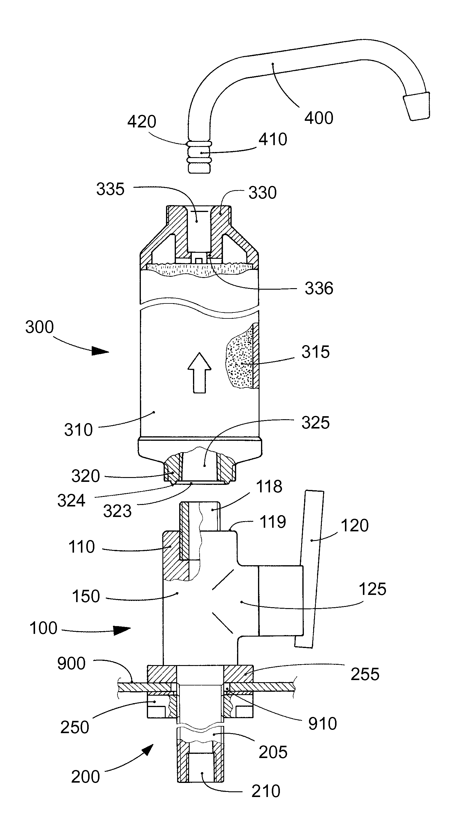
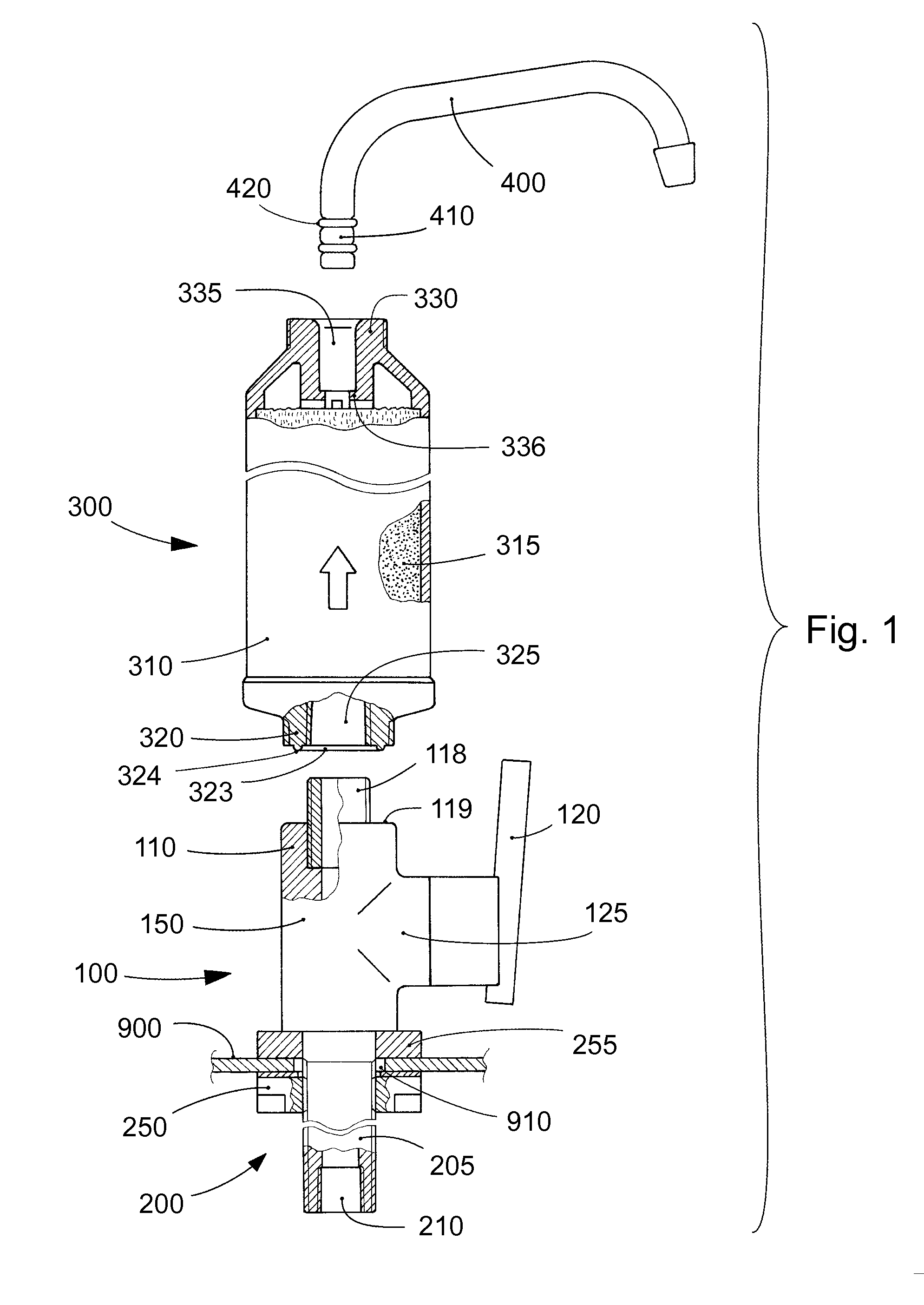
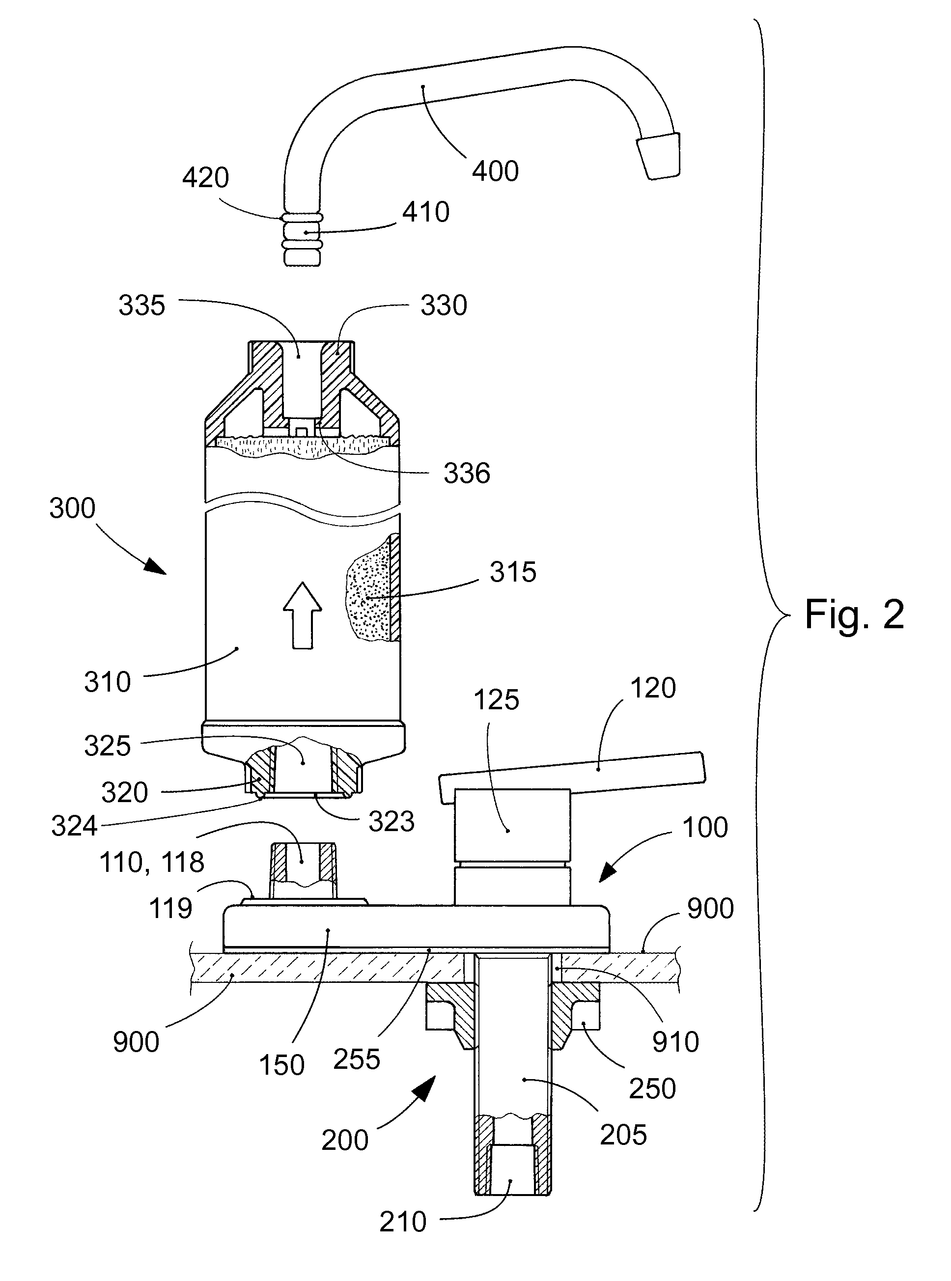
[0136]The inventive water treatment assembly is generally in the form of a water filter faucet. Exemplary embodiments of the inventive filter faucet are shown in FIGS. 1, 2, 3, and 4, according to the invention. In general, each embodiment includes a valve assembly 100 generally in the form of a faucet assembly, a combined means 200, a disposable inline filter 300, and a water spout 400.

[0137]In FIGS. 1 and 2, the valve assembly 100 is shown mounted on a sink or similar countertop mounting surface 900 generally similar to a countertop faucet assembly. The valve assembly 100 is conjoined with a combined means 200 extended downward and operatively fitted through a hole 910 in the mounting surface 900. The combined means 200 operatively fastens the valve assembly 100 to the mounting surface 900 and couples with a potable cold water supply conduit 800, shown in FIG. 3. The combined means 200 is shown comprising a mounting support 255, an externally threaded pipe 205 alternatively known ...


PUM

PropertyMeasurementUnit
depthaaaaaaaaaa
atmospheric pressureaaaaaaaaaa
diameteraaaaaaaaaa

Abstract

A water treatment assembly generally in the form of a filter faucet generally of the type mounted on a sink or similar countertop surface. The water treatment assembly generally comprises a mounted valve assembly, an inline water filter, and a water spout. The inline water filter is configured intermediate the mounted valve assembly and the spout. The inline water filter has a watertight shell comprising a water inflow port and a water outflow port that allow the filter to be used as a readily replaceable and disposable modular filter cartridge. The filter inflow port allows for releasable fluid engagement with the valve assembly. The filter outflow port comprises a fitting for receiving the spout. Water flow through the filter and spout is controlled by the valve assembly. The combined assembly permits the new use of standard components improved in a cost effective manner to form a reliable filter faucet.

Description

CROSS-REFERENCE TO RELATED APPLICATIONS[0001]This application incorporates by reference and claims priority to U.S. Provisional Patent Application No. 61 / 517,166 filed Apr. 14, 2011.BACKGROUND OF THE INVENTION[0002]The present invention generally relates to water treatment and filtration devices for installation on a sink surface or countertop in conjunction with residential plumbing systems for improving the quality of potable water for human consumption. More particularly to a countertop filter faucet comprising a water treatment element incorporated therein.[0003]Water consumers are increasingly aware that public water supplies are contaminated with many undesirable chemicals and microorganisms capable of impairing the health of those who consume the water. For example, water supplies in rural agricultural areas often contain nitrate, herbicide, and pesticide runoff from crop treatment. Most municipalities add chlorine to guard against pathogens in the public water supply. There ...

Claims


Application Information

Patent Timeline
Patent Type & Authority Applications(United States)
IPC IPC(8): B01D35/02B01D29/88B01D27/00
CPCE03C1/0404E03C2201/40C02F2307/06C02F2201/004C02F2201/006C02F1/003B01D35/02
Inventor LONIEWSKI, GRZEGORZNIGHTLINGER, SCOTT ANTHONYLONIEWSKA, AGNIESZKA MONIKALONIEWSKI, PIOTR
Owner LONIEWSKI GRZEGORZ
Why Eureka
Try Eureka