Driving assist system for vehicle

a technology for driving assistance and vehicles, applied in the direction of controlling members, external condition input parameters, driver input parameters, etc., can solve the problem of great reaction force for stepping down upon the accelerator pedal

Inactive Publication Date: 2006-01-03
NISSAN MOTOR CO LTD
View PDF33 Cites 63 Cited by
  • Summary
  • Abstract
  • Description
  • Claims
  • Application Information

AI Technical Summary

Benefits of technology

[0005]However with the above described type of system, even if, for example, the operator is intentionally catching up with the preceding vehicle in order to ov

Problems solved by technology

However with the above described type of system, even if, for example, the operator is intentionally catching up with the preceding vehicle in order to overt

Method used


Image

  • Driving assist system for vehicle
  • Driving assist system for vehicle
  • Driving assist system for vehicle

Examples


first embodiment

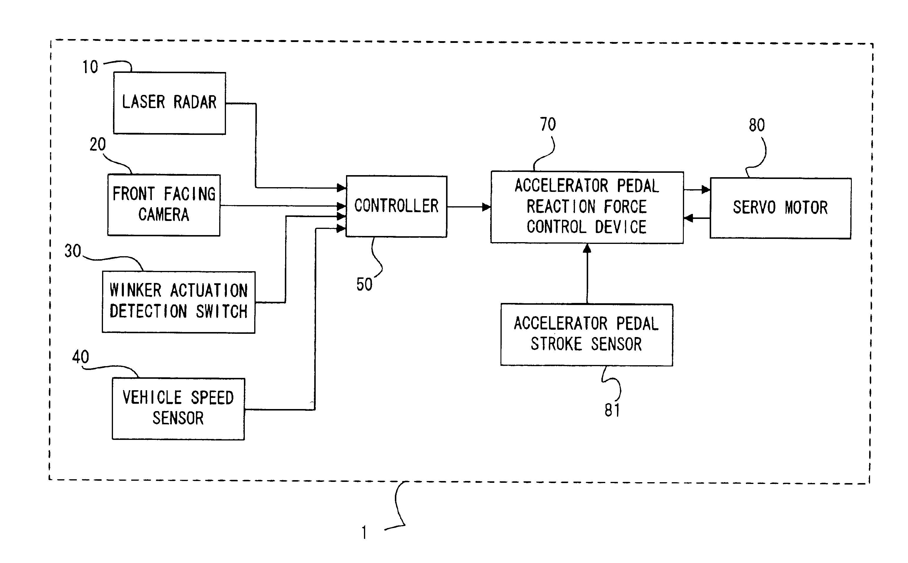
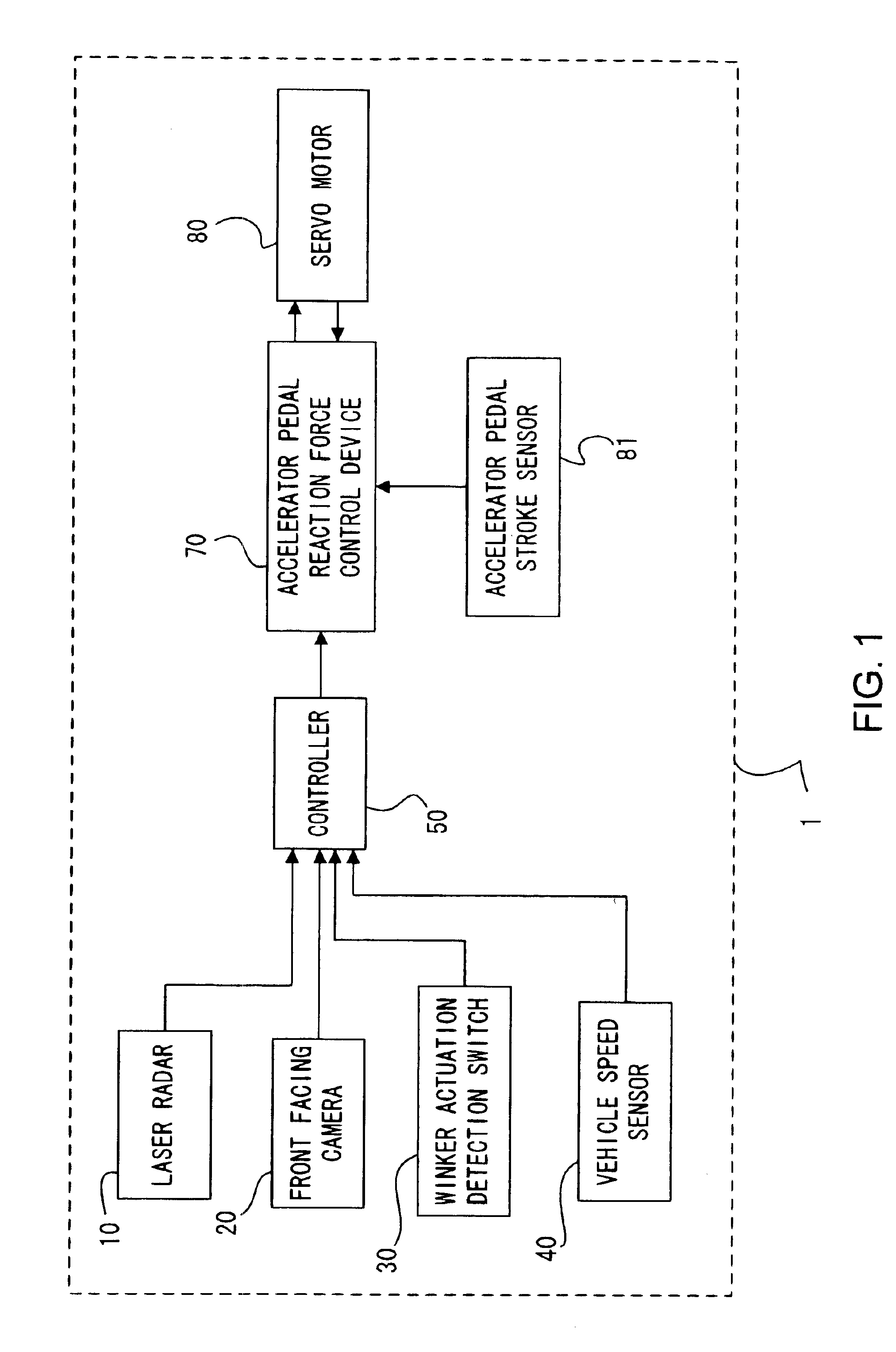
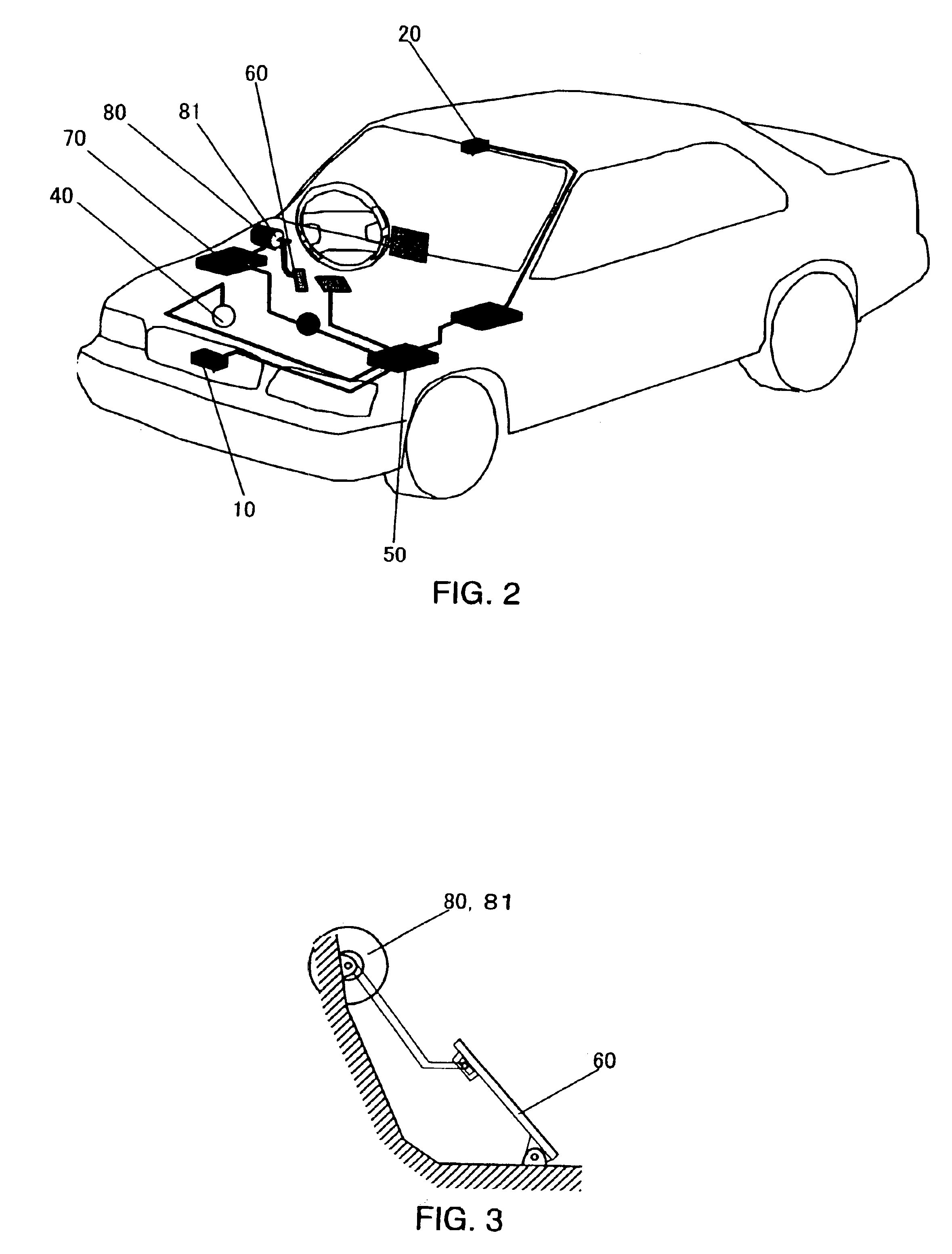
[0027]FIG. 1 is a block diagram showing the structure of a driving assist system 1 for a vehicle according to the first preferred embodiment of the present invention, while FIG. 2 is a structural diagram of a vehicle to which this driving assist system 1 is fitted.

[0028]First, the structure of this vehicle driving assist system 1 will be explained.

[0029]A laser radar 10 is mounted to a front grille of the vehicle. Such a laser radar 10 is of a type which can scan horizontally and laterally about 6 degrees to each side of an axis parallel to the vehicle longitudinal centerline, propagates infrared pulses forward, and receives the radiation reflected by an obstacle, such as a rear bumper of a vehicle in front of the subject vehicle. This laser radar 10 provides the vehicle separation or distance, and the relative velocity or speed between the subject vehicle and the preceding vehicle. Such a laser radar 10 outputs the vehicle distance and the relative speed between the subject vehicle...

second embodiment

[0084]In the following, the driving assistance system for a vehicle according to the second preferred embodiment of the present invention will be explained. The physical structure of the vehicle driving assist system according to this second preferred embodiment is the same as that of the first preferred embodiment shown in FIGS. 1 and 2, and accordingly its description will be curtailed. Herein, the explanation will principally focus upon the points in which this second preferred embodiment differs from the first preferred embodiment.

[0085]FIG. 10 is a figure showing a characteristic of the reaction force increase amount ΔF with respect to the risk potential RP (RP-ΔF characteristic), in this second preferred embodiment of the present invention. In FIG. 10, the RP-ΔF characteristic when no intention on the part of the operator to change the vehicle lane is detected is shown by the broken line, while the RP-ΔF characteristic when an intention on the part of the operator to change th...

third embodiment

[0109]In the following, the driving assist system for a vehicle according to the third preferred embodiment of the present invention will be explained.

[0110]FIG. 13 is a figure showing the interior structure of a controller which is incorporated in this vehicle driving assist system 2 according to the third preferred embodiment of the present invention, and structures in its neighborhood. In FIG. 13, elements which correspond to elements of the first preferred embodiment shown in FIGS. 1 through 4 and described above are denoted by the same reference numerals, and their explanation will herein be curtailed. Here, the explanation will focus upon the point of difference between this third preferred embodiment and the first preferred embodiment.

[0111]As shown in FIG. 13, this vehicle driving assist system 2 according to the third preferred embodiment of the present invention comprises a risk potential modification section 56 which changes or modifies the risk potential RP according to ...


PUM


Abstract

A vehicle driving assist system comprises a travel situation detection device that detects a vehicle condition and a traveling environment around a subject vehicle; a risk potential calculation device that calculates a risk potential around the subject vehicle based upon detection results of the traveling situation detection device; an accelerator pedal reaction force calculation device that calculates an accelerator pedal reaction force command value based upon the risk potential which is calculated by the risk potential calculation device; an accelerator pedal reaction force generation device that generates an actuation reaction force for an accelerator pedal, according to the accelerator pedal reaction force command value which is calculated by the accelerator pedal reaction force calculation device; a driving intention detection device that detects a driving intention of an operator of the subject vehicle; and an accelerator pedal reaction force modification device that adjusts the actuation reaction force to be generated for the accelerator pedal, based upon a detection result of the driving intention detection device.

Description

BACKGROUND OF THE INVENTION[0001]1. Field of the Invention[0002]The present invention relates to a driving assist system for a vehicle which assists an operator to drive a vehicle, to a method thereof, and to a vehicle which is equipped with such a system.[0003]2. Description of the Related Art[0004]As a system which assists operation by an operator to drive a vehicle, there is known the one disclosed in Japanese Patent Laid Open Publication No. H 10-166889. This system is one which changes the actuation reaction force for the accelerator pedal based upon the distance between the vehicle in front and the subject vehicle which is detected by a vehicle distance detection device. For example, with this system, when the distance between vehicles is less than a predetermined value, an accelerator pedal actuation reaction force is added, in order to provide a warning to the operator.SUMMARY OF THE INVENTION[0005]However with the above described type of system, even if, for example, the op...

Claims


Application Information

Patent Timeline
IPC IPC(8): G08B23/00B60K26/02B60K26/04B60K28/02B60K31/00B60R21/00B60T7/22B60T17/18B60W30/08B60W30/095B60W40/02B60W40/08B60W50/14B60W50/16F02D11/02F02D11/10F02D29/02G08G1/16
CPCB60T17/18B60W40/02B60W50/16G05G1/30B60T7/22B60K26/021Y10T74/20534B60W2050/143B60W2420/52B60W2420/62B60W2520/10B60W2540/20B60W2550/10B60W2550/20B60W2550/308F02D11/105B60W2554/00B60W2554/801B60W2554/802B60W2554/804
Inventor KUGE, NOBUYUKIYAMAMURA, TOMOHIRO
Owner NISSAN MOTOR CO LTD
Why Eureka
Try Eureka