Push-button switch

a push-button switch and push-button technology, applied in the direction of electric devices, contact mechanisms, electric lifts, etc., can solve the problem of high production cost and achieve the effect of improving design

Active Publication Date: 2006-01-10
ORMON CORP +1
View PDF6 Cites 25 Cited by
  • Summary
  • Abstract
  • Description
  • Claims
  • Application Information

AI Technical Summary

Benefits of technology

[0006]It is therefore an object of this invention to provide a push-button switch using a relatively small number of light sources but capable of providing illuminations with an improved design.

Problems solved by technology

With a prior art bush-button switch thus structured, a relatively large number of LEDs are usually employed as light sources in order to illuminate the whole of the operating surface of the push-button and it has been one of the causes of its high production cost.

Method used


Image

  • Push-button switch
  • Push-button switch
  • Push-button switch

Examples


Embodiment Construction

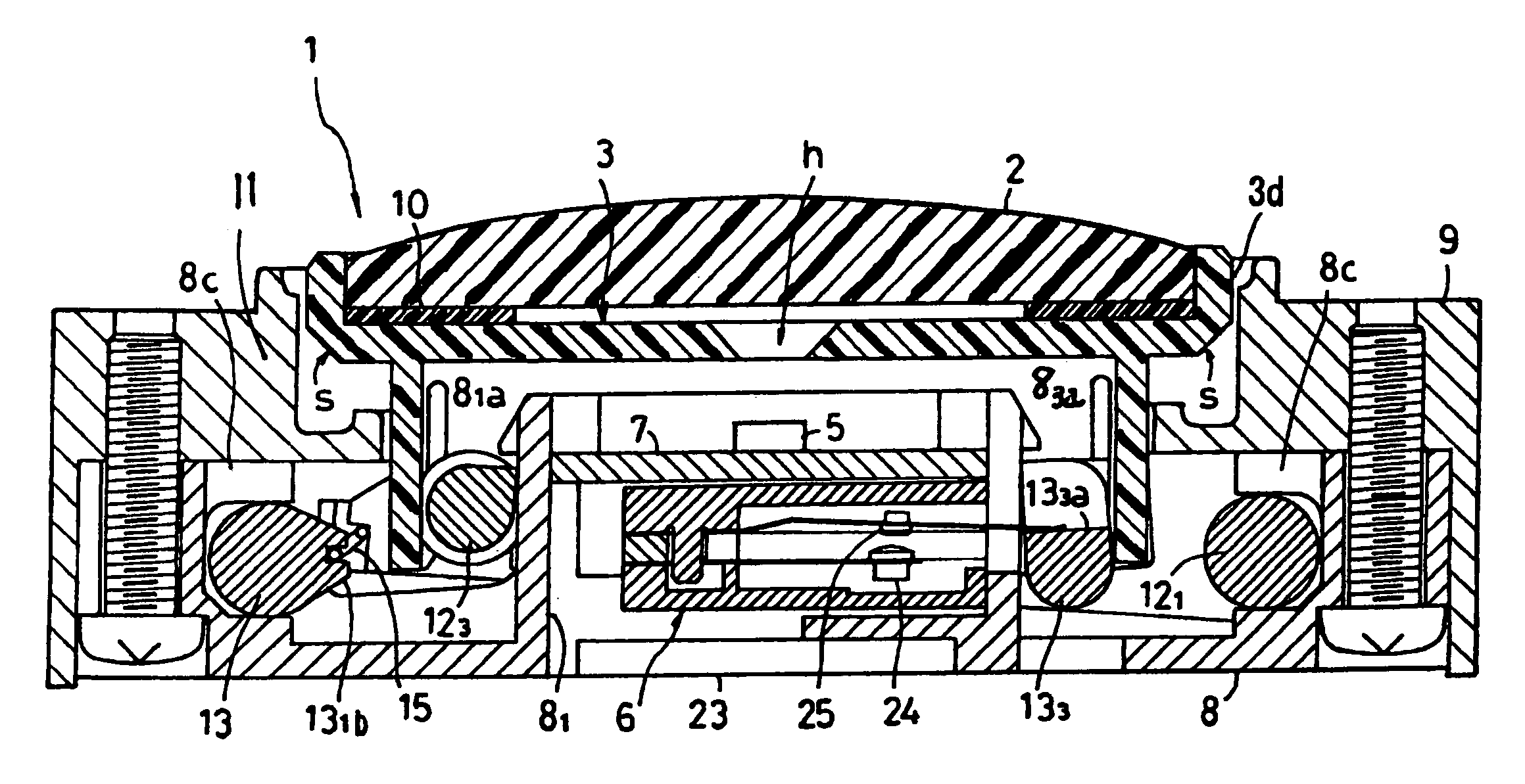
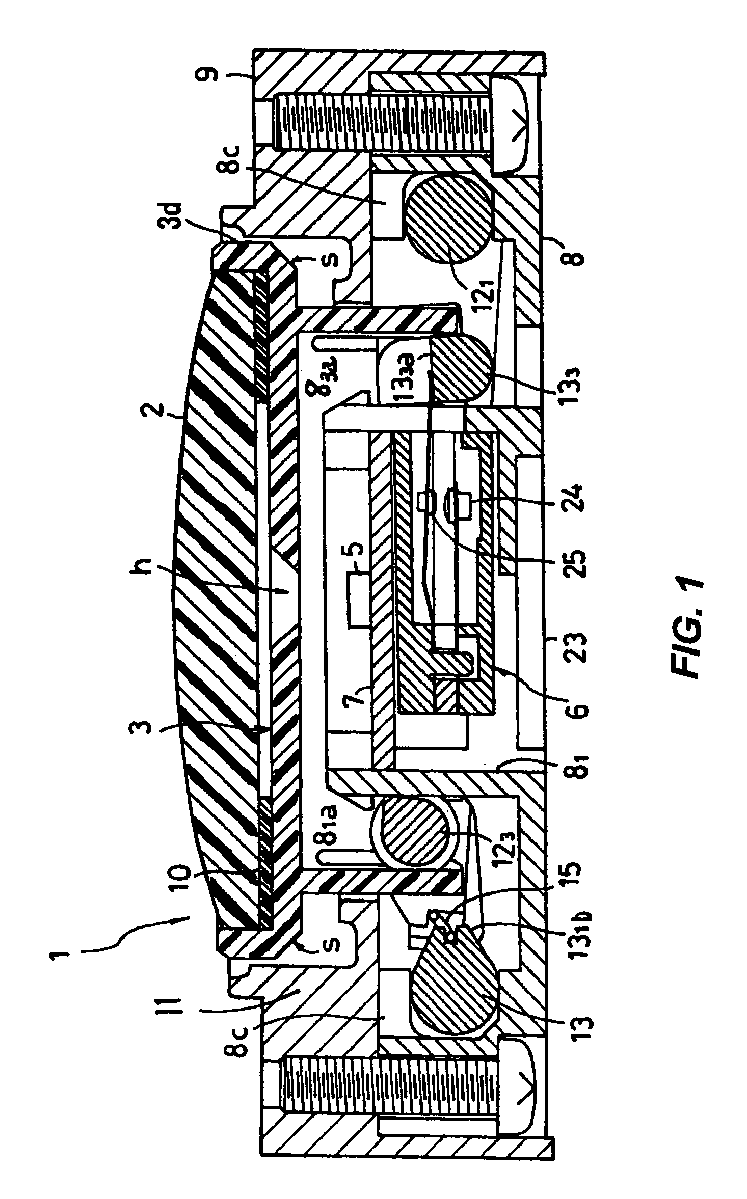
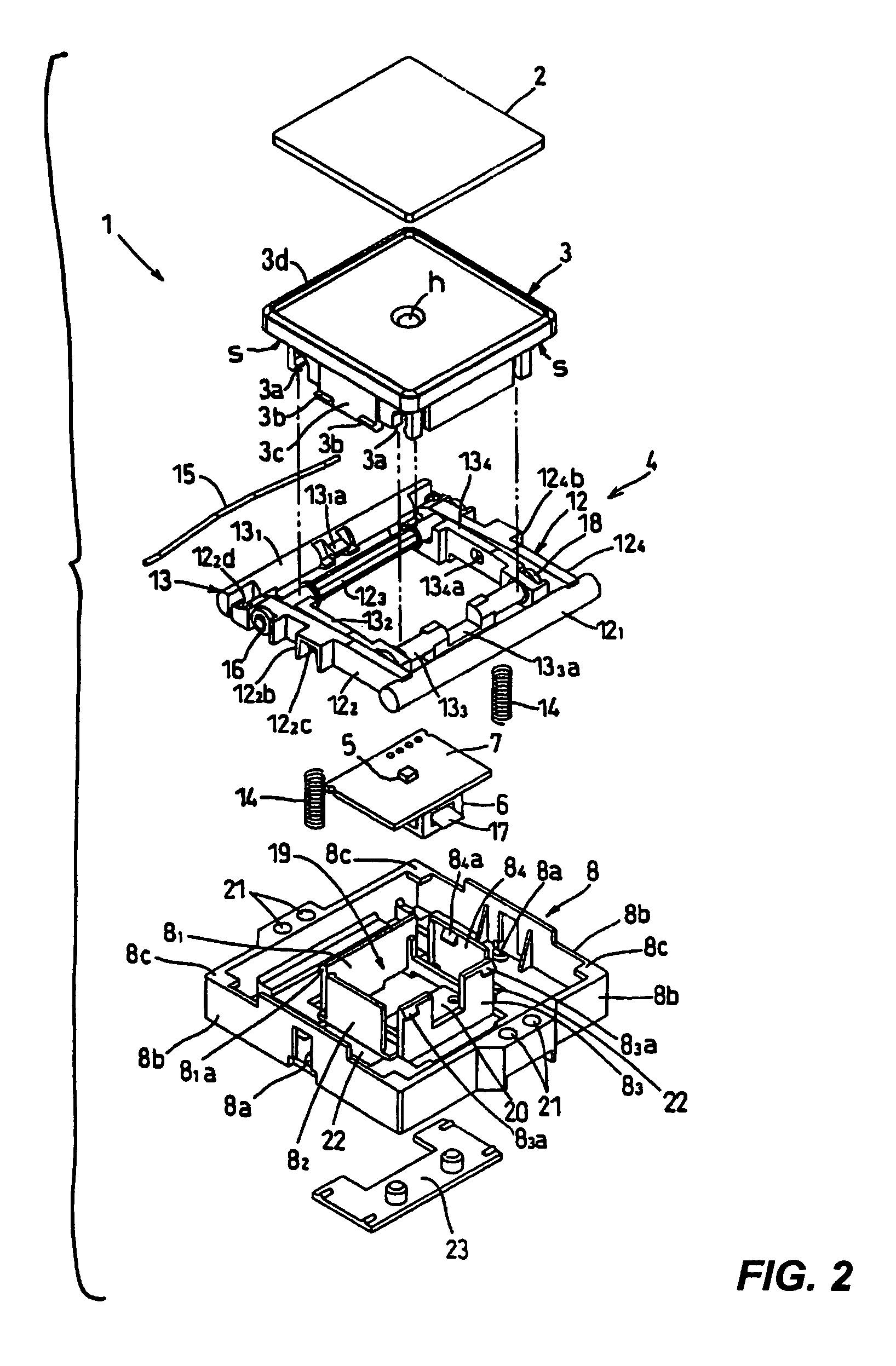
[0031]The invention is described next by way of an example. FIG. 1 is a sectional view of a push-button switch 1 embodying this invention and FIG. 2 is its exploded diagonal view. This push-button switch 1 is of the illumination type adapted to be used as an indicator switch for an elevator for indicating the upward or downward direction and to be set conveniently on a wall surface beside the entrance to the elevator.

[0032]As basic components, this push-button switch 1 is provided with a plunger 3 having a cap 2 attached thereto, a link mechanism 4 to be described below for displacing the plunger 3 in the direction of operation (the up-down direction in FIG. 1) without tilting it, a circuit board 7, a base member 8 for containing the circuit board 7, the link mechanism 4 and a cover 9 which engages and is screwed to the base member 8 from outside. The cap 2 serves as a pressing member having an operating surface. The circuit board 7 has electronic components such as a chip LED 5 ser...


PUM


Abstract

A push-button switch has a plunger to be pressed so as to activate its main body supported by a base member. A cap serving as a pressing member is on an outer edge portion of the plunger. The outer periphery of the cap is surrounded by a frame part of a lens member made of a transparent resin material such that the light from a light source disposed near the center of the plunger is guided to the upper edge part of the frame part.

Description

[0001]Priority is claimed on Japanese Patent Application P2003-174428 filed Jun. 19, 2003.BACKGROUND OF THE INVENTION[0002]This invention relates to a push-button switch and more particularly to a push-button switch of an illuminating type which may be set conveniently on a wall surface beside the entrance to an elevator for indicating an upward or downward direction.[0003]As disclosed in FIGS. 2 and 3 of Japanese Patent Publication Tokkai 11-314861, for example, a push-button switch is generally structured such that a switch main body is activated as the operating surface of the push-button is pressed so as to push and displace a plunger and contains an illuminator using a light source such as an LED for displaying that the switch main body has been activated.[0004]With a prior art bush-button switch thus structured, a relatively large number of LEDs are usually employed as light sources in order to illuminate the whole of the operating surface of the push-button and it has been on...

Claims


Application Information

Patent Timeline
Patent Type & Authority Patents(United States)
IPC IPC(8): H01H9/18H01H13/02H01H3/12H01H9/16H01H13/14
CPCH01H3/122H01H2219/0622B66B1/462H01H13/14H01H9/16
Inventor MORITA, KAZUAKITOBITA, KOKICHIHIRAI, YOSHIKAZUMINE, TERUYUKISATO, TADASHI
Owner ORMON CORP
Why Eureka
Try Eureka