Gas flow restricting cathode system for ion implanter and related method

a cathode system and ion implanter technology, applied in the manufacture of electrode systems, electric discharge tubes/lamps, instruments, etc., can solve the problems of increasing gas, short lifespan, and relatively small mass of filaments

Active Publication Date: 2006-01-10
VARIAN SEMICON EQUIP ASSOC INC
View PDF3 Cites 3 Cited by
  • Summary
  • Abstract
  • Description
  • Claims
  • Application Information

AI Technical Summary

Benefits of technology

[0011]A second aspect of the invention is directed to a cathode system for use in a source of an ion implanter system, the cathode system comprising: a cathode element configured to extend through an aperture in a wall of an arc chamber of the ion implanter system, the cathode element and the aperture having a spacing therebetween; a heated filament to heat the cathode element; and a flange restricting a gas flow through the spacing, the flange extending outwardly relative to an outer periphery of the cathode element to restrict the gas flow.

Problems solved by technology

One problem with this approach, however, is that the filament has a relatively small mass and, accordingly, a short lifespan due to its direct exposure to the plasma.
Spacing 28, inter alia, increases the gas required to operate the system and presents a gas leakage problem.
Typically, however, the insulator cannot withstand the high temperatures generated by the cathode, and consequently generates off-gasses.
The off-gas is highly undesirable because of its effect on the plasma and downstream components.
Increased gas leakage can lead to coating of the high voltage system components and an increase high voltage break down, glitch rate and general ion beam instability.
As a result, more frequent cleaning of the system is required.
All of the above-described issues affect the cost of operation and reliability.

Method used


Image

  • Gas flow restricting cathode system for ion implanter and related method
  • Gas flow restricting cathode system for ion implanter and related method
  • Gas flow restricting cathode system for ion implanter and related method

Examples


Embodiment Construction

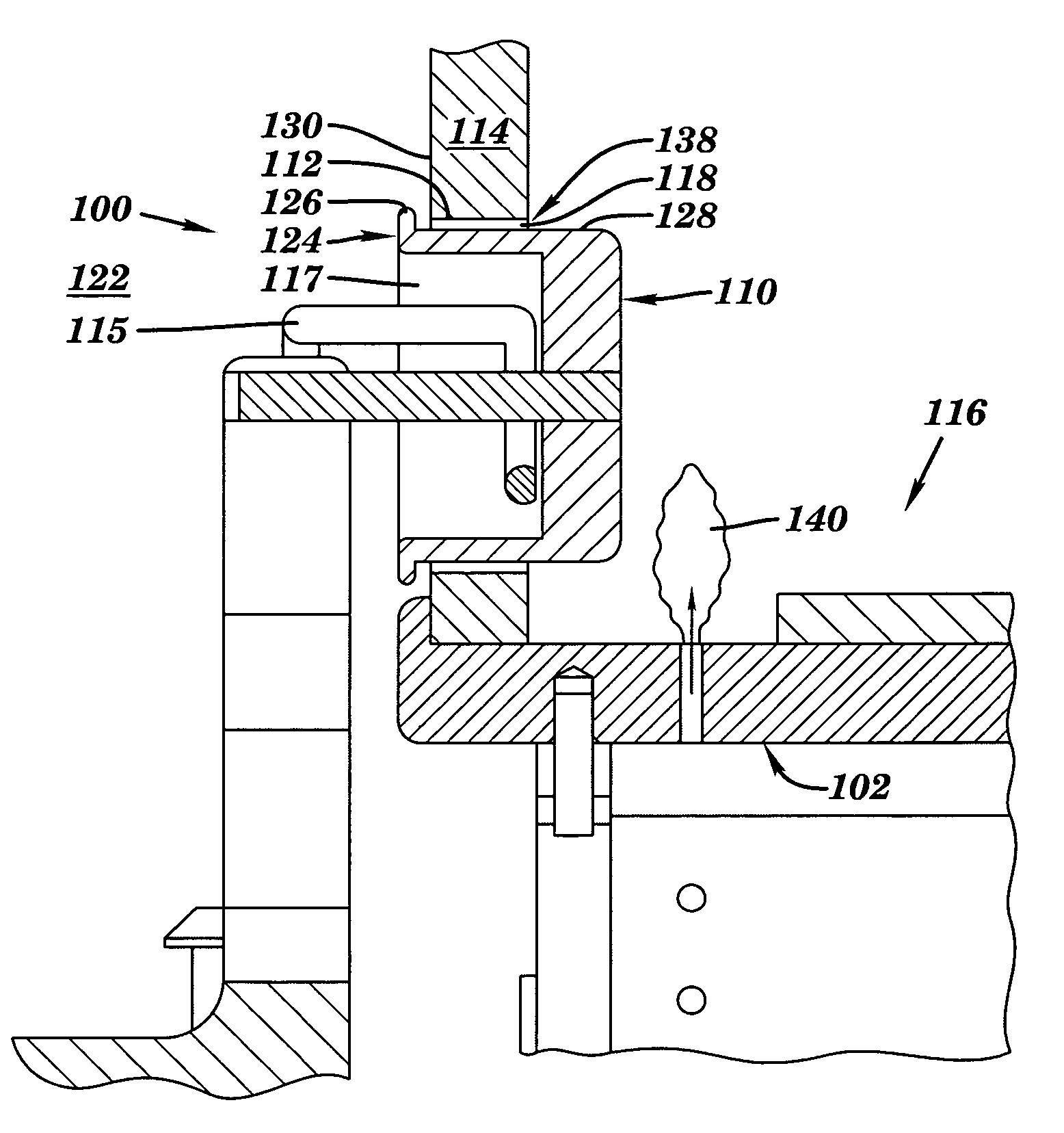
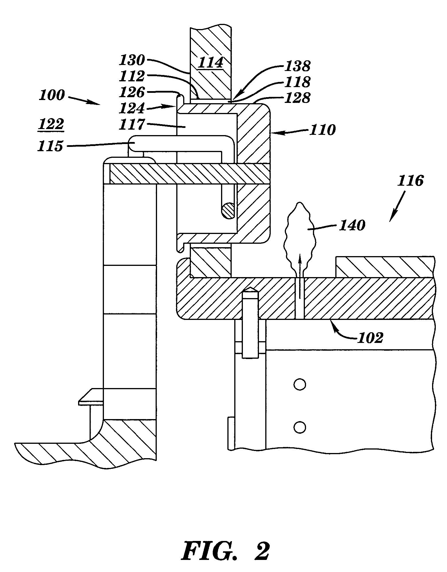
[0022]With reference to the accompanying drawings, FIG. 2 illustrates a cathode system 100 for use in a source 102 of an ion implanter system according to the invention. Cathode system 100 includes a cathode element 110 configured to extend through an aperture 112 in a wall 114 of an arc chamber 116 of the ion implanter system. A heated filament 115 is positioned adjacent cathode element 110 in a hollow area 117 of the element, i.e., filament 115 extends within hollow area 117. Power supplies that: heat filament 115, provide a bias voltage between filament 115 and cathode element 110, and provide an arc voltage between cathode element 110 and arc chamber 116, have been omitted for clarity. Heated filament 115 generates sufficient energy to emit electrons from a portion thereof, which are propelled against hollow area 117 of cathode element 110 by a bias voltage. As a result, cathode element 110 becomes hot until it reaches a point where it emits electrons into arc chamber 116. The e...


PUM

PropertyMeasurementUnit
gas conductanceaaaaaaaaaa
massaaaaaaaaaa
current electricityaaaaaaaaaa

Abstract

A cathode system having a cathode element configured to extend through an aperture in a wall of an arc chamber of an ion implanter system. A gas flow through a spacing between the cathode element and the aperture is restricted by a restriction member. A method of ionizing a source gas and a cathode element incorporating the restriction member are also provided.

Description

BACKGROUND OF THE INVENTION[0001]1. Technical Field[0002]The present invention relates generally to ion implanter systems. In particular, the invention relates to a gas conductance restricting cathode system for use in an ion implanter system.[0003]2. Related Art[0004]Ion implanter systems include a component referred to as a source, which generates an ion beam. An ion beam source receives a gas from a gas source and ionizes the gas into a plasma by exposing the gas to energetic electrons. The energetic electrons may be generated in a number of ways. One conventional approach to ionize the gas has been to directly expose the gas to a heated filament in an arc chamber. The heated filament may include, for example, tungsten. One problem with this approach, however, is that the filament has a relatively small mass and, accordingly, a short lifespan due to its direct exposure to the plasma.[0005]In order to address this problem, indirect heated cathode (IHC) sources have been implemente...

Claims


Application Information

Patent Timeline
Patent Type & Authority Patents(United States)
IPC IPC(8): H01J37/08
CPCH01J37/08H01J37/3171H01J2237/082H01J2237/061H01J2237/06308H01J2237/006
Inventor LOW, RUSSELL J.OLSON, JOSEPH C.BERGERON, CURT D.COBB, ERIC R.BURGESS, JEFFREY A.
Owner VARIAN SEMICON EQUIP ASSOC INC
Why Eureka
Try Eureka