Motion compensated upconversion for plasma displays

a plasma display and upconversion technology, applied in the direction of instruments, television systems, signal generators with optical-mechanical scanning, etc., can solve the problems of large area flicker, many motion artifacts, and many motion artifacts, so as to reduce large area flicker and reduce motion artifacts

Inactive Publication Date: 2006-01-10
SAMSUNG SDI CO LTD
View PDF4 Cites 27 Cited by
  • Summary
  • Abstract
  • Description
  • Claims
  • Application Information

AI Technical Summary

Benefits of technology

[0013]It is an object of the present invention to provide a method for displaying moving pictures on a PDP display with a relative simple system that shows very little motion artifacts.
[0030]A method according to the invention reduces large area flicker with reduction of motion artifacts, like blur or double edges.

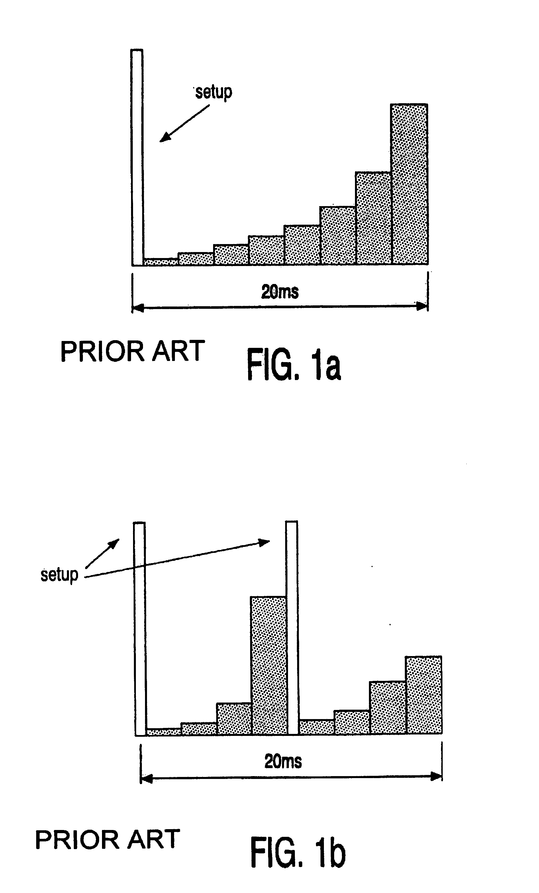
Problems solved by technology

Plasma display panels suffer from several motion artifacts.
However, such a sub-field distribution will cause more motion artifacts, such as double / colored edges or motion blur.
In cathode ray tube (CRT) screens, large area flicker and motion artifacts are a well-known problem too.
This algorithm can give very good moving picture quality, but its implementation is very complex.

Method used


Image

  • Motion compensated upconversion for plasma displays
  • Motion compensated upconversion for plasma displays
  • Motion compensated upconversion for plasma displays

Examples


first embodiment

[0048]FIG. 3 is a block diagram of an apparatus of the present invention. The apparatus, e.g., a television receiver, comprises a set and a panel. Both set and panel contain processing modules. The panel (i.e., the actual screen) receives Red Green Blue (RGB) signals from a tuner in the set.

[0049]Interlaced YUV input data 20 is de-interlaced and up-converted by means of a frame rate converter 22. Several commercial available modules exist, see “Video Processing for multimedia systems”, by G. de Haan, University Press Eindhoven, ISBN 90-9014015-8.

[0050]The output is a progressive 100 Hz video stream 24. This video stream 24 is in standard YUV format. It is converted, by YUV converter 26, to a 100 Hz RGB signal 28. This 100 Hz RGB signal is transferred from the set to the panel, which is indicated by a dashed line. The next step is a gamma / Floyd Steinberg (FS) dithering performed by a video processor 30. The output of the video processor 30 is a processed 100 Hz progressive RGB signal...

second embodiment

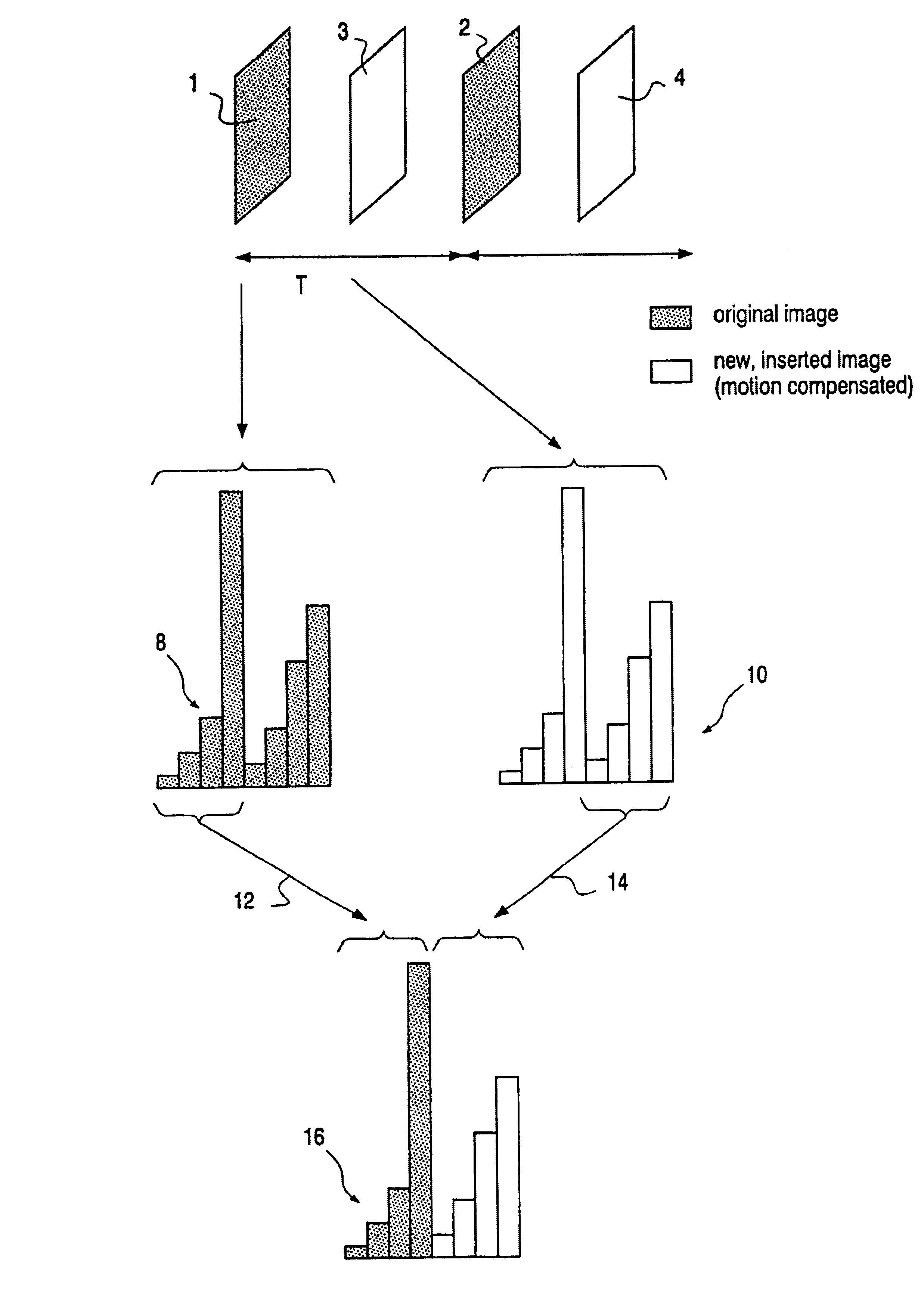
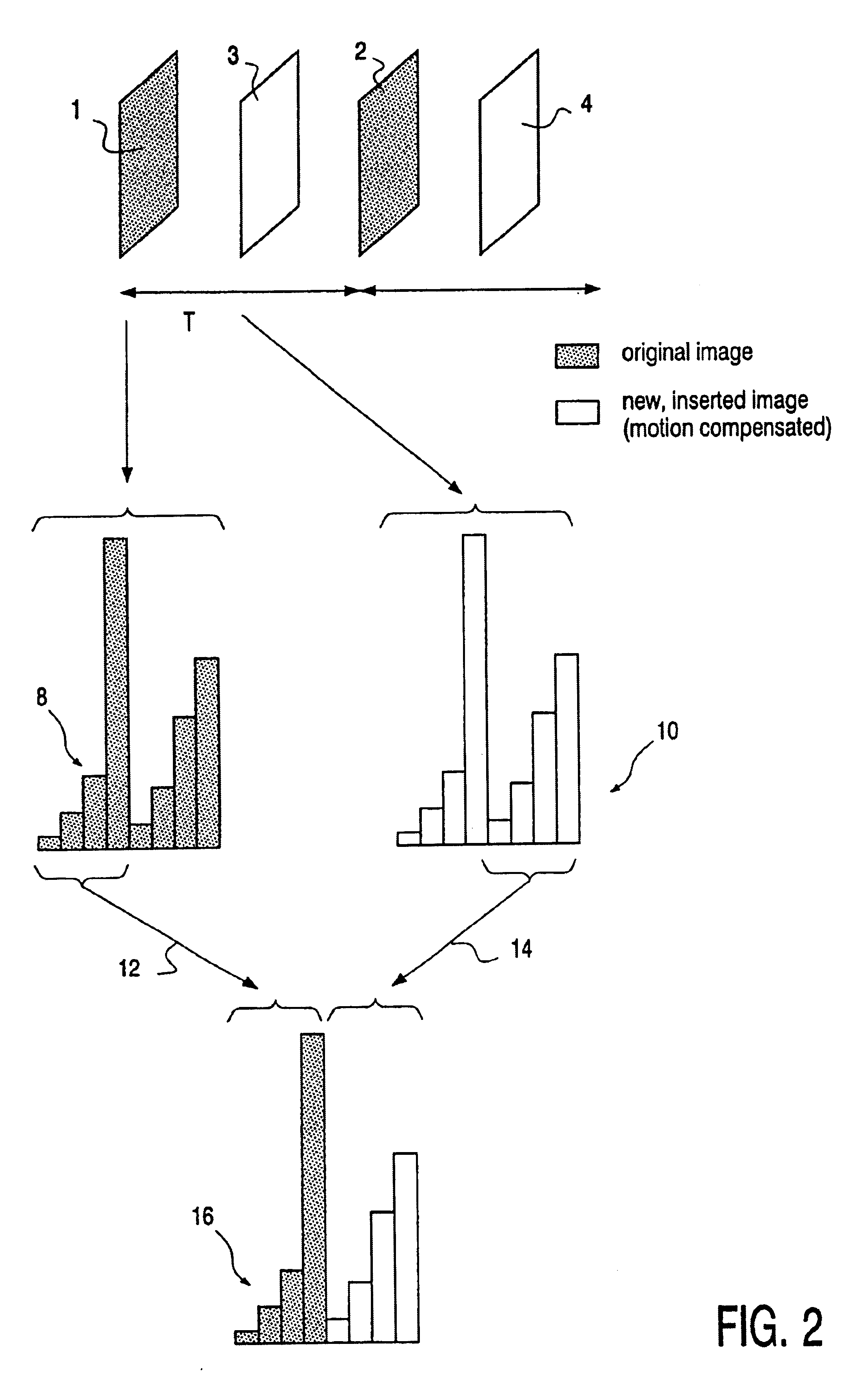
[0052]In FIG. 4, a block diagram of the apparatus of the present invention is shown. Interlaced YUV input data 50 is de-interlaced by a frame rate converter 52. In frame rate converter 52, motion vectors 53 are calculated out of two consecutive original images using a state-of-the-art motion estimation process. Unlike in FIG. 3, no up-conversion is performed in this module. The outgoing signal is a progressive 50 Hz video stream 54. This video stream 54 is in YUV format. It is converted, by YUV converter 56, to a 50 Hz RGB signal 58. This 50 Hz RGB signal 58 is transferred from the set to the panel, which is indicated by a dashed line. The next step is a gamma / FS dithering performed by a video processor 60. The output of the video processor 60 is a processed 50 Hz progressive RGB signal 62. Next, sub-field generation is performed by a up-conversion / sub-field generation module 64. At this point, an up-conversion is performed by inserting new images between original images using the m...


PUM


Abstract

A method for driving a PDP minimizes motion artifacts, like blur and double edges, by using an up-conversion to preferably 100 Hz as in CRTs with Natural Motion, combined with an LSC sub-field distribution. Sub-field groups from two images are combined to form a field for a display image.

Description

BACKGROUND OF THE INVENTION[0001]1. Field of the Invention[0002]The present invention relates to a method of driving a plasma display panel, the method comprising the steps of:[0003]receiving a series of consecutive original images; and[0004]distributing information from each original image over a first plurality of sub-fields.[0005]The invention also relates to a device for driving a plasma panel display and to a display apparatus.[0006]2. Description of the Related Art[0007]Plasma display panels (PDPS) are widely used for flat TV screens. These panels are simple to form a large unit, emit light by themselves, provide high display quality and achieve high response speed. In order to display an image on such a display unit, the so-called “sub-field driven method” is used. One image frame is shown in a number of successive periods called sub-fields. During a sub-field, an amount of light is emitted which is dependent on the weight of the sub-field. Each sub-field has a different weig...

Claims


Application Information

Patent Timeline
Patent Type & Authority Patents(United States)
IPC IPC(8): G09G3/28G09G3/296G09G3/20G09G3/293G09G3/294G09G3/30H04N5/44H04N5/70
CPCG09G3/2022G09G3/2803H04N7/0132H04N5/70H04N7/012G09G3/2937G09G3/2944G09G2310/0229G09G2320/0261G09G2320/0266G09G2320/0247G09G3/296G09G3/30
Inventor HOPPENBROUWERS, JURGEN JEAN LOUISVAN WOUDENBERG, ROEL
Owner SAMSUNG SDI CO LTD
Why Eureka
Try Eureka