Camera control system, image pick-up server, client, control method and storage medium therefor

a control system and camera technology, applied in the field of camera control system, can solve the problems of camera not being installed at such a location, image area in which privacy problems may arise,

Inactive Publication Date: 2006-01-10
CANON KK
View PDF6 Cites 146 Cited by
  • Summary
  • Abstract
  • Description
  • Claims
  • Application Information

AI Technical Summary

Benefits of technology

[0004]Accordingly, an object of the present invention is to provide a camera control system whic

Problems solved by technology

However, there is the danger that an imaging area in which problems arise in terms of privacy may fall w

Method used


Image

  • Camera control system, image pick-up server, client, control method and storage medium therefor
  • Camera control system, image pick-up server, client, control method and storage medium therefor
  • Camera control system, image pick-up server, client, control method and storage medium therefor

Examples


first embodiment

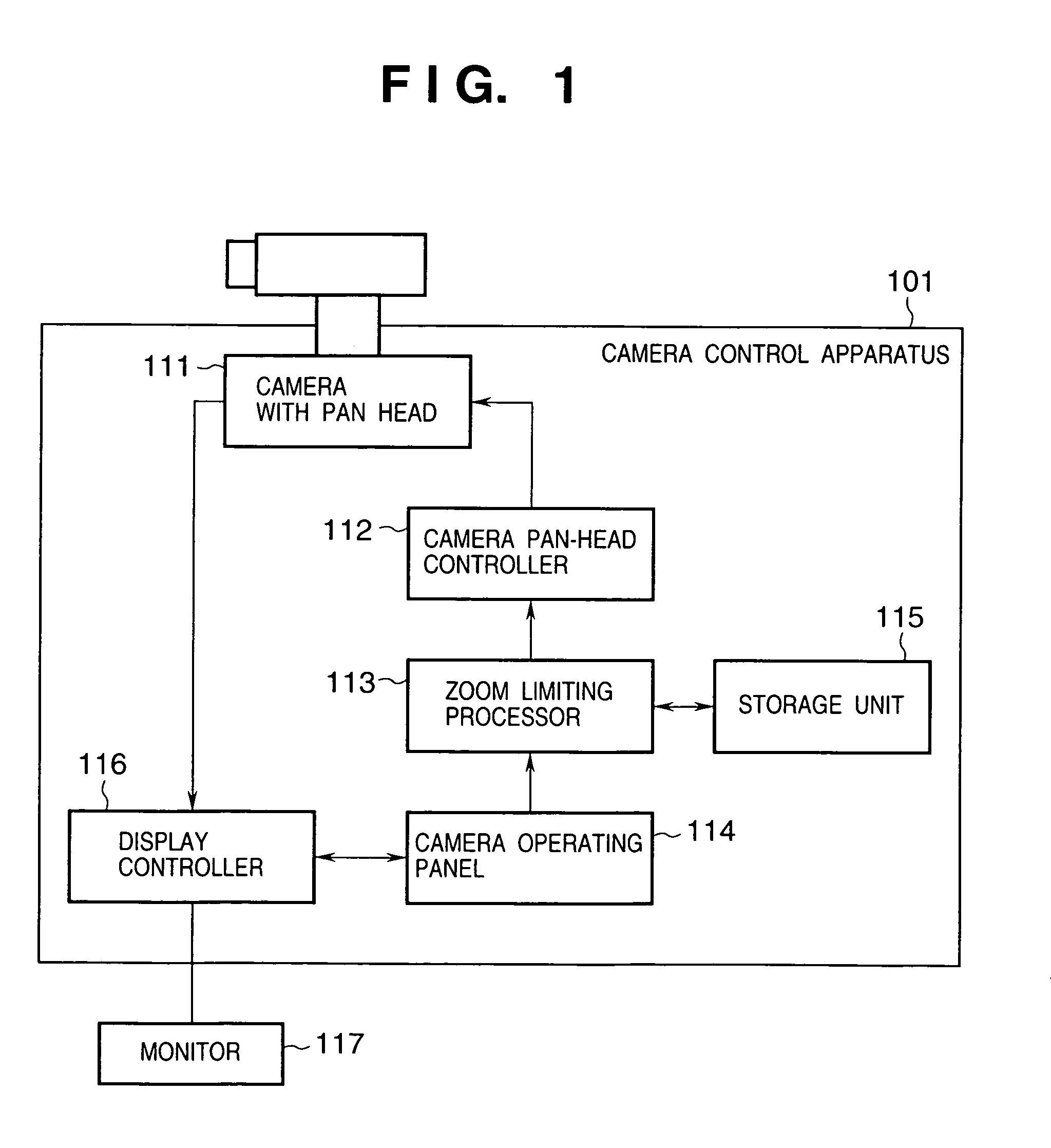
[0049]FIG. 1 is a block diagram showing a camera control apparatus 101 according to this embodiment. A camera 111 equipped with a pan head is panned and tilted by controlling the pan head, thereby controlling the shooting direction of the camera. The camera 111 is equipped with a zoom lens the imaging angle of view of which can be changed. The image picked up by the camera 111 is output to a display controller 116. The latter executes predetermined signal processing and then displays the captured image on a monitor 117. The monitor 117 is constituted by a bitmap display or the like.

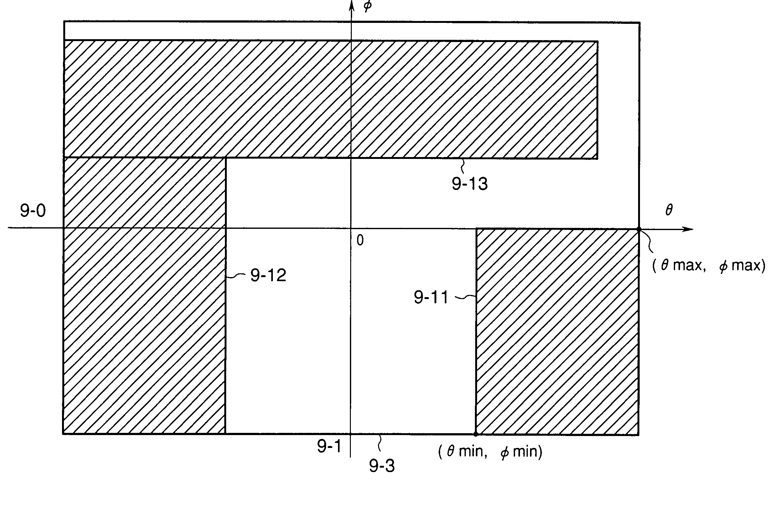
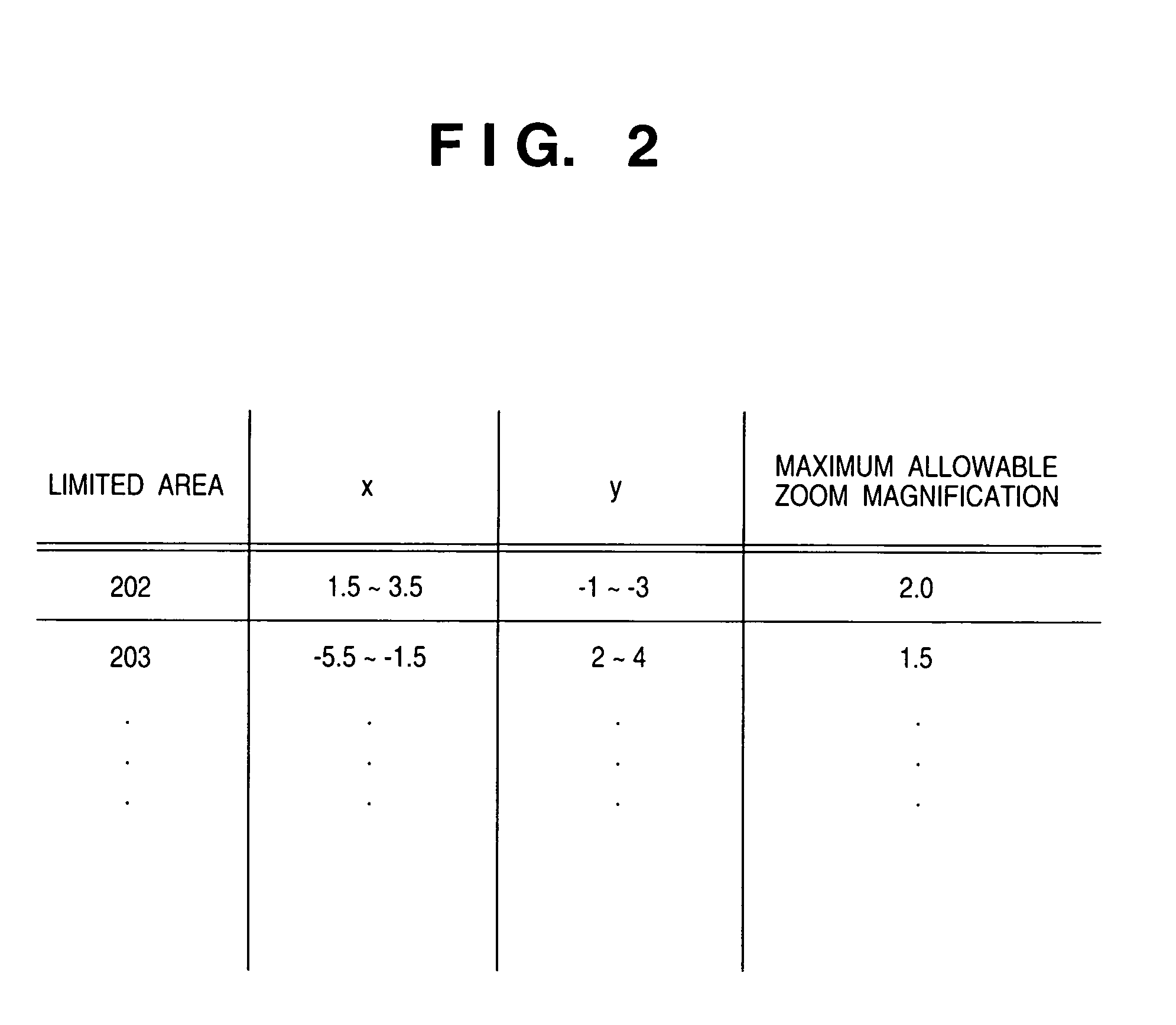
[0050]A camera operating panel 114, which comprises a mouse or keyboard (not shown), etc., is capable of inputting commands for controlling panning tilting and zooming of the camera 111. A zoom limiting processor 113 determines whether to limit zoom magnification in dependence upon the pan, tilt and zoom control commands entered from the camera operating panel 114. A storage unit 115, which comprises a RA...

second embodiment

[0066]A second embodiment of the present invention will now be described in detail with reference to the accompanying drawings.

[0067]Briefly stated, the second embodiment is such that when a client looks through a camera that has been connected to a camera server, it appears just as if there are a plurality of cameras.

[0068]FIG. 10 of a system according to the second embodiment.

[0069]The system shown in FIG. 10 includes a camera server 1-1, a display control terminal (referred to as a “client”) 1-2 for displaying video from the camera server 1-1 and remotely controlling a camera, and a network 1-3 for connecting the camera server 1-1 and client 1-2.

[0070]The camera server 1-1 captures video from a video camera 1-11, distributes the video to the client 1-2, accepts camera control commands from the client 1-2 and controls the zoom magnification of the video camera 1-11 and a movable pan head 1-12. (Operating the movable pan head 1-12 makes it possible to change the pan and tilt angles...


PUM


Abstract

Provided is a camera control system which will not invade one's privacy even if a camera is located where there is a problem in terms of privacy. To accomplish this, the system is provided with an input unit for inputting a control command for controlling shooting direction or zoom magnification of the camera, a calculation unit for calculating, on the basis of the control command input by the input unit, an area to be imaged by the camera, a limiting unit for limiting a control range of the zoom magnification of the camera in a case where the imaging area of the camera calculated by the calculation unit overlaps a prescribed area; and a control unit for controlling the zoom magnification of the camera so as to fall within the control range, which has been limited by the limiting unit, in a case where the zoom magnification of the camera exceeds the control range limited by the limiting unit.

Description

BACKGROUND OF THE INVENTION[0001]This invention relates to a camera control system, which is capable of controlling a remote camera, ideal for application to surveillance cameras, etc.[0002]A camera control system for controlling the shooting direction and zoom magnification of a remote camera via a network has already been proposed by the assignee of the present applicant.[0003]However, there is the danger that an imaging area in which problems arise in terms of privacy may fall within the field of view of the camera. The camera cannot be installed at such a location for this reason.SUMMARY OF THE INVENTION[0004]Accordingly, an object of the present invention is to provide a camera control system which will not invade one's privacy even at a location where there is a problem in terms of privacy.[0005]According to the present invention, the foregoing object is attained by providing a camera control apparatus for controlling shooting direction and zoom magnification of a camera, comp...

Claims


Application Information

Patent Timeline
IPC IPC(8): H04N5/232
CPCG06T1/0007H04N5/23296H04N5/23206G06T2200/24H04N23/661H04N23/631H04N23/69H04N23/695
Inventor MORITA, KENJIKAWAI, TOMOAKI
Owner CANON KK
Why Eureka
Try Eureka