Portable bivouac shelter

a bivouac and portable technology, applied in the field of portable bivouac shelters, can solve the problems of heavy, expensive, and a large portion of the material of the bivouac bag, and achieve the effect of reducing the weight and bulk of the bag

Inactive Publication Date: 2006-01-17
TURNER TIMOTHY D
View PDF31 Cites 20 Cited by
  • Summary
  • Abstract
  • Description
  • Claims
  • Application Information

AI Technical Summary

Benefits of technology

[0008]An object of the present invention, therefore, is to provide a portable, bivouac shelter system that solves problems in state-of-the-art camping gear and reduces the weight and bulk thereof by combining the upper portion of a bivouac bag with a sleeping pad. The pad is integral therewith and forms the bottom of the shelter—thus eliminating a major portion of the material of the bivouac bag—which is typically heavy and expensive.
[0009]Another object of the invention is to provide a portable bivouac shelter that can be simply unrolled and occupied almost immediately, by saving the time otherwise needed to arrange a sleeping pad inside the bivouac bag—since the sleeping pad is no longer an extra item.
[0010]Another object of the invention is to provide a shelter that includes a canopy, attached to the bivouac bag, that can provide protected storage space for toiletry items, etc., and can enable the user to sit upright, while protected from the elements—without the weight and bulk of a tent.
[0011]Another object of the invention is to provide a shelter in which the canopy is supported by segmented wands, wherein the wands (except for one) are all of the same length and the segments of each wand are foldably fastened together by internal elastic strands. Hence, the wands can be easily installed in the canopy without the user's having to make wand-length choices or locate parts.
[0012]Another object of the invention is to provide a shelter wherein the canopy can easily be completely closed, partially opened, or completely opened.
[0013]Another object of the invention is to provide a shelter wherein shallow punctures in the floor of a preferred embodiment of the shelter will not destroy its effectiveness as a watertight shelter.

Problems solved by technology

The pad is integral therewith and forms the bottom of the shelter—thus eliminating a major portion of the material of the bivouac bag—which is typically heavy and expensive.

Method used


Image

  • Portable bivouac shelter
  • Portable bivouac shelter
  • Portable bivouac shelter

Examples


second embodiment

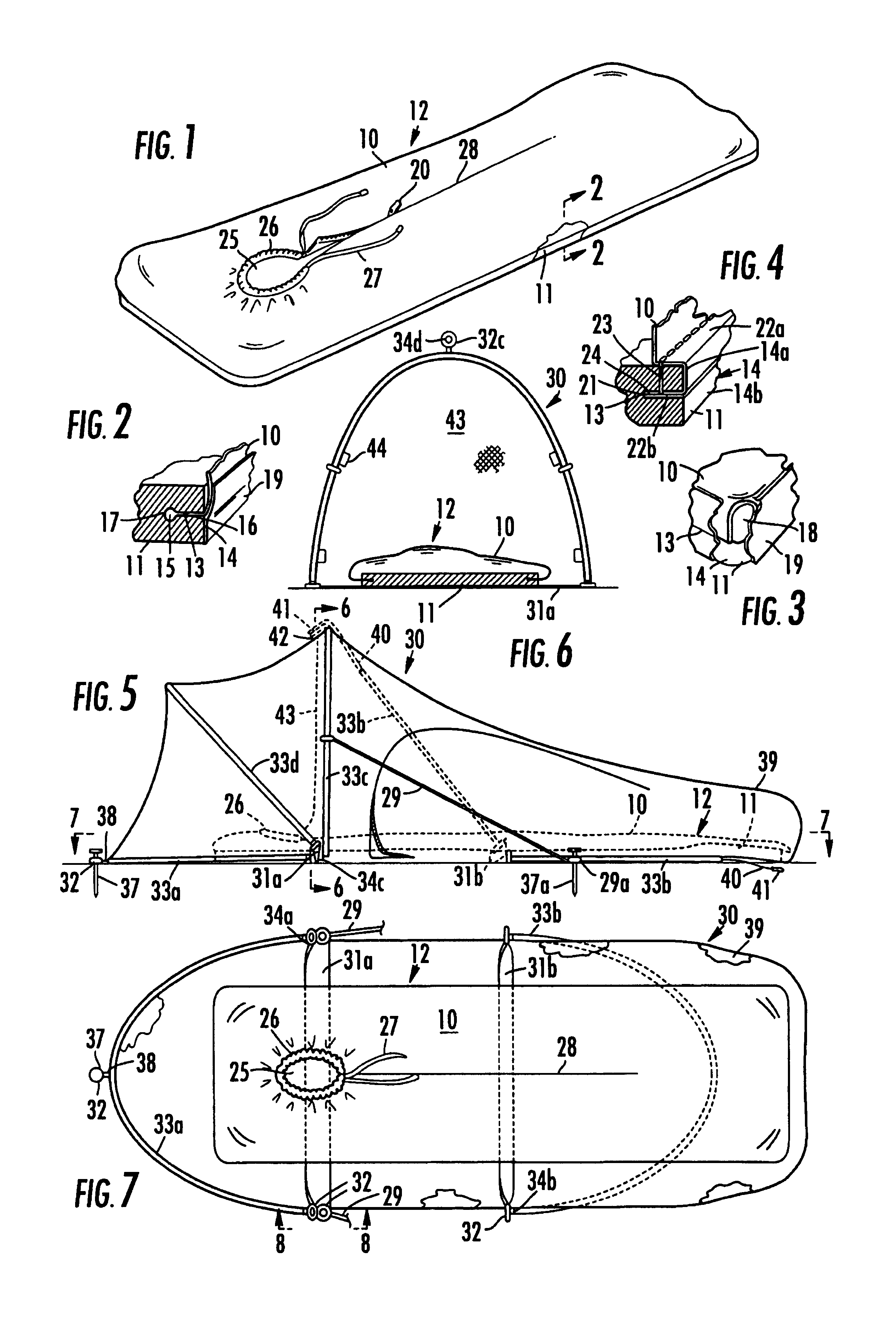
[0034]In the invention (FIGS. 5-9) a rain shelter or canopy 30 is attached to the pad 11 via a first strap 31a and a second strap 31b that extend beneath the pad 11 and are attached to it transversely to its major axis at approximately the positions of the user's shoulders and hips, respectively. The first strap 31a holds two grommets 32 in each of its end portions, and the second strap 31b holds one grommet 32 in each of its end portions (FIGS. 7 and 8). The canopy 30 can be of any light-weight, water-proof material. Whereas the upper shell 10 of the bivouac bag is preferably air-and-vapor breathable to avoid water condensation in contact with an enclosed sleeping bag, this is not necessary for the canopy 30, which normally permits adequate ventilation around the bivouac bag 12 to prevent such condensation. As conventionally used, “air-and-vapor-breathable but waterproof” refers to any of the materials on the market that are impervious to water, but admit passage therethrough of ai...

third embodiment

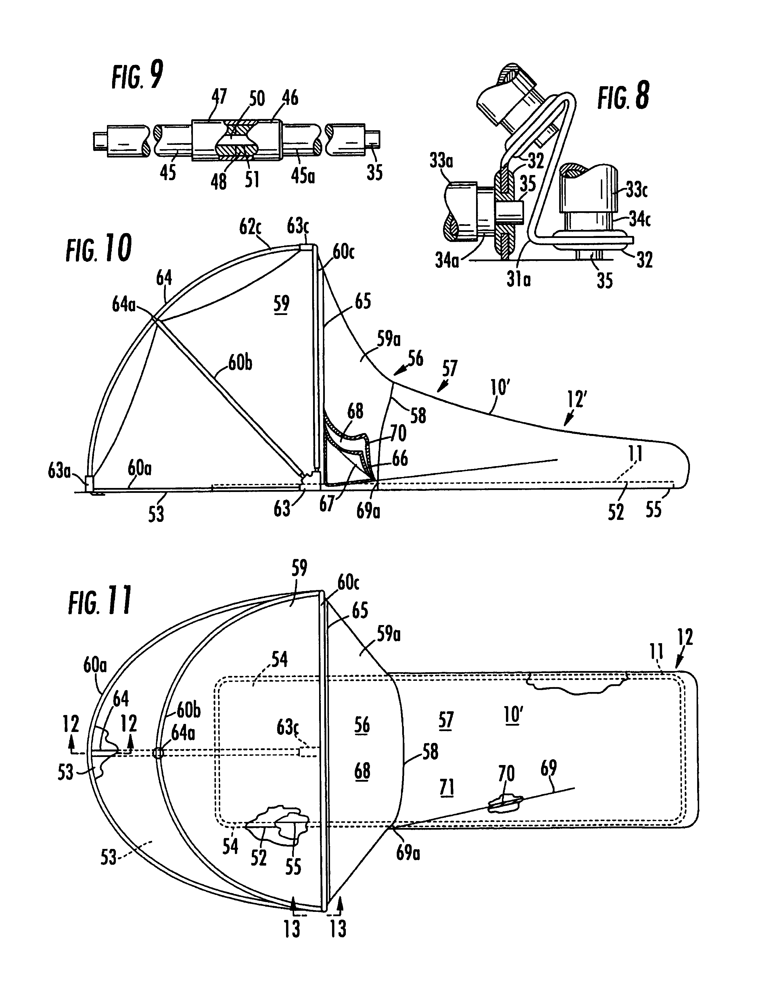
[0041]the invention is shown in FIGS. 10-13. The rectangular, plastic-foam sleeping pad 11 (as described above) is bonded, at its bottom edges 52, to the floor 53 of the shelter (FIG. 11). The shelter floor 53 has a large, rectangular opening 54 slightly smaller than the pad 11, so that its edges overlap the edges of the pad by about one inch on all four sides—the overlap 55 being bonded to the bottom of the pad 11. The shelter is divided into a canopy section 56 and a foot-end section 57 by a juncture 58 (although the pad 11 is continuous between the sections). The foot-end section 57 has an outer shell 10′, as described above that is preferably made of water-proof but air-and-vapor-breathable material; and the canopy section 56 is preferably made of waterproof nylon fabric, or other waterproof material, also as described above. Similarly, the foot-end section 57 of the shelter is of a tubular configuration. However, since it is joined to the canopy section 56, it is not closeable ...

fourth embodiment

[0046]the invention is shown in FIG. 14. A canopy 30″, having a rectangular base, is formed of canopy material 30a, as described above, stretched over two long, flexible wands 34″ fastened together at their apexes, and to the inside of the top of the canopy 30 by a hook-and-loop strap 72 fastened thereto. The ends of the wands 34″ are seated in pockets 63′ fastened into the bottom corners of the canopy 30″. The head-end portion of the bivouac bag 12 (which is the same as shown in FIG. 1) extends through an opening 73 in the side 74 of the canopy 30″ toward the user's feet, and the shell 10′ of the bivouac bag 12 is joined to the opening 73 with a watertight seal. A floor 75 of the canopy material 30a surrounds, and is fastened to, the head-end portion of the sleeping pad by one of the methods previously described. However, the floor 75 in this embodiment covers only a portion of the rectangular base of the canopy 30″. Adjacent the head end of the bivouac bag 12, the floor 75 is bent...


PUM


Abstract

A shelter is formed by joining a resilient sleeping pad at its edges to a thin, flexible, waterproof, vapor-breathable shell. The sleeping pad, being the floor of the shelter, eliminates material otherwise used for this purpose. An opening in the shell for the user's face, is edged with a sleeve containing a drawstring for closing the opening to the extent desired. A zippered separation in the shell extends from the opening, to provide easy access into the shelter. A canopy, attached to the shelter, is supported above a user by long, resilient wands attached to the canopy material. Various embodiments are disclosed for combining a canopy with the basic shelter, for supporting the canopy above the user, and for providing entry into the resulting shelter.

Description

CROSS-REFERENCES TO RELATED APPLICATIONS[0001]Not applicable.FEDERALLY SPONSORED RESEARCH OR DEVELOPMENT[0002]Not applicableREFERENCE TO MICROFICHE APPENDIX[0003]Not applicableBACKGROUND OF THE INVENTION[0004]1. Field of the Invention[0005]This invention relates to personal, portable, bivouac shelters. More specifically, it relates to such shelters in combination with sleeping pads, wherein the sleeping pad, itself, forms a part of the shelter or enclosure—in which a sleeping bag and other items may be enclosed along with the occupant.[0006]2. Description of the Related Art[0007]A portable shelter is usually the bulkiest and heaviest part of a backpacker's gear for extended hiking trips. It is also the most difficult to handle in inclement weather. Traditionally, the portable shelter has comprised a light-weight tent for protection against the elements and insects, a sleeping bag, and a foam or inflatable sleeping pad that served the dual purpose of providing a soft surface on the u...

Claims


Application Information

Patent Timeline
Patent Type & Authority Patents(United States)
IPC IPC(8): A47G9/08E04H15/32E04H15/38
CPCE04H15/38E04H15/324
Inventor TURNER, TIMOTHY D.
Owner TURNER TIMOTHY D
Why Eureka
Try Eureka