Bale dewiring system

a bale and bale technology, applied in the field of bale dewiring system, can solve the problems of material coming lodged in the system, time-consuming manual operation, and limited space in which the material can expand,

Inactive Publication Date: 2006-01-17
SIGNODE IND GRP
View PDF15 Cites 15 Cited by
  • Summary
  • Abstract
  • Description
  • Claims
  • Application Information

AI Technical Summary

Problems solved by technology

Moreover, such manual operations can be time consuming and can possibly cause injury.
As such, the space into which the material can expand is limited.
In the event that the material expands to a volume greater than anticipated, the material can be come lodged in the system and disrupt operations.
While this functions well to sever the wire, it tends to burn the recycling materials due to the friction generated by the blade rotating through the material.

Method used


Image

  • Bale dewiring system
  • Bale dewiring system
  • Bale dewiring system

Examples


Embodiment Construction

[0033]While the present invention is susceptible of embodiment in various forms, there is shown in the drawings and will hereinafter be described a presently preferred embodiment with the understanding that the present disclosure is to be considered an exemplification of the invention and is not intended to limit the invention to the specific embodiment illustrated.

[0034]It should be understood that the title of this section of this specification, namely, “Detailed Description Of The Invention”, relates to a requirement of the United States Patent Office, and does not imply, nor should be inferred to limit the subject matter disclosed herein.

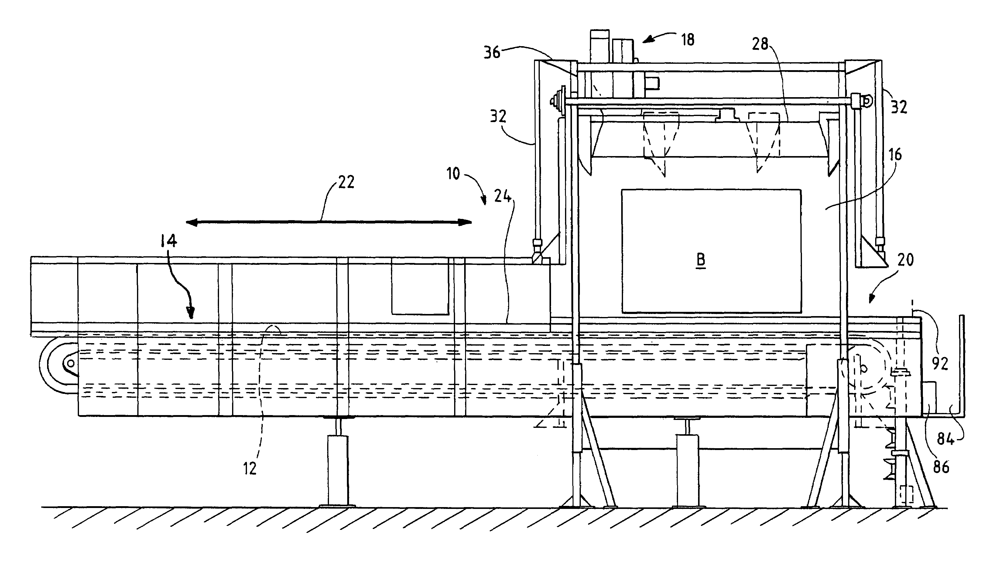
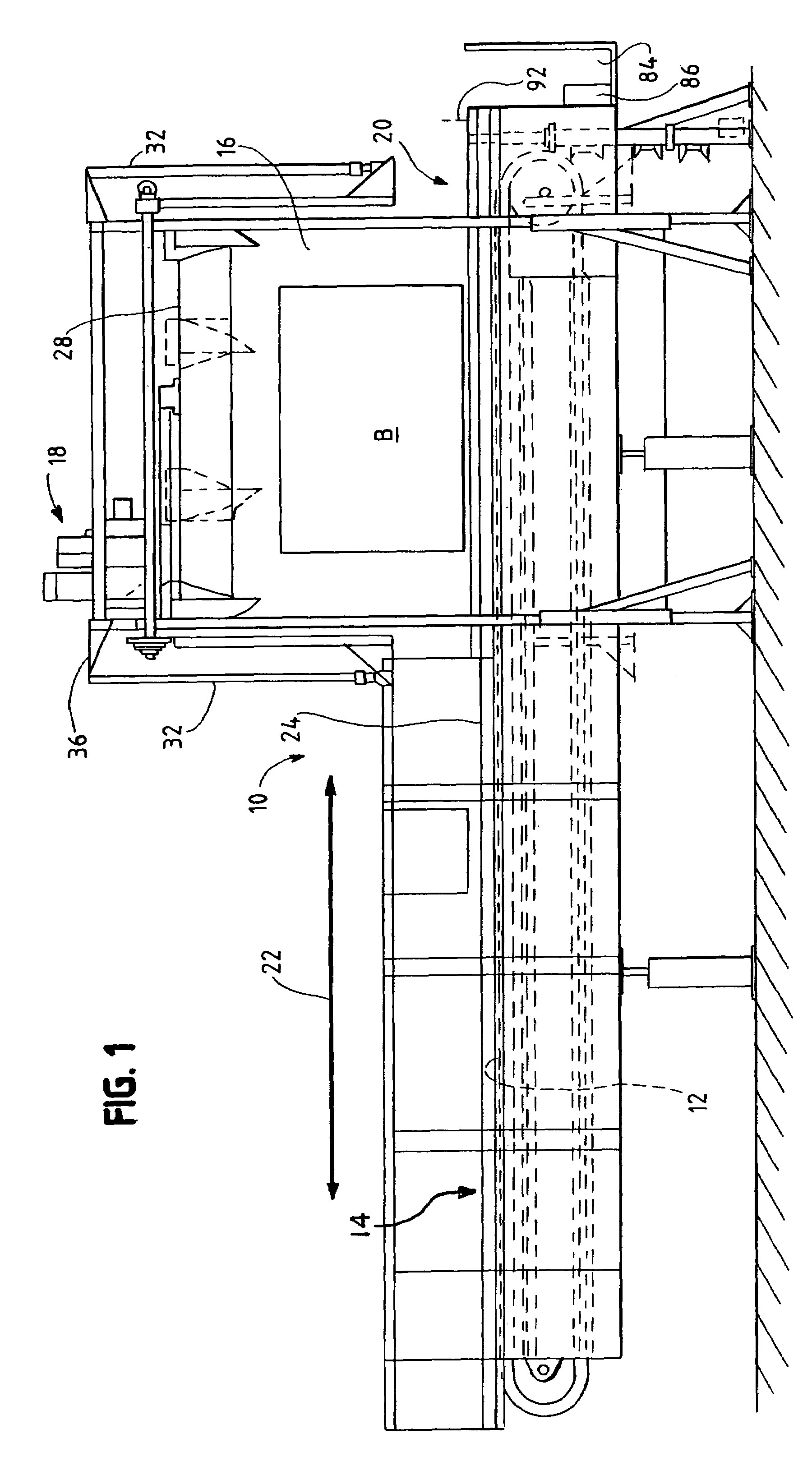
[0035]Referring now to the figures and in particular to FIG. 1, there is shown a bale dewiring system 10 embodying the principles of the present invention. The system 10 is configured to safely remove wire W (or strapping) from a compressed bale B with minimal operator interface. Bales can be, for example, cardboard, plastic or fiber material th...


PUM

PropertyMeasurementUnit
compressaaaaaaaaaa
volumeaaaaaaaaaa
lengthaaaaaaaaaa

Abstract

A bale dewiring system for removing one or more wires wrapped around a bale from the bale includes a frame, a bale receiving region defined by the frame and defining a longitudinal direction, an upper compression platen mounted to the frame for vertically moving into contact with the bale to compress the bale, and side compression plates movable in the longitudinal direction into contact with the bale to compress the bale. A rail is operably mounted to the upper platen for vertical movement therewith. A cutting assembly is mounted to the rail for movement along the rail for cutting the one or more wires. A winding assembly is operably mounted to the frame and includes a rotating winding element having a wire receiving region and a wire winding region for winding the cut wires to remove the wires from the bale.

Description

BACKGROUND OF THE INVENTION[0001]The present invention relates to a system for handling and dewiring bales. More particularly, the present invention is directed to a system for removing wire from bales, controlling decompression of the bale and collecting the removed wire.[0002]Many items are bundled or baled for handling, transport and storage. For example, recycled materials are often gathered and bundled together, in a bale, for ease of transportation and handling. In the case of plastics for recycling, the bale of material for recycling is maintained by wire that is wrapped around the material to compress the material.[0003]The material is often well compressed. As such, as the wire is severed or removed from the bale, the material will rapidly expand to a less compressed (or decompressed) state. In order to use the material, e.g., feed the material into a recycling process, the wire must be removed and the material loosened. Subsequent processes can include sorting, foreign obj...

Claims


Application Information

Patent Timeline
Patent Type & Authority Patents(United States)
IPC IPC(8): B65B69/00
CPCB65B69/0025Y10T29/5139Y10T29/49821Y10S83/909
Inventor COVINGTON, DONALD T.SZADZIEWICZ, PAUL R.WITCZAK, STANISLAW
Owner SIGNODE IND GRP
Why Eureka
Try Eureka