Valve for inflatable objects

a valve and inflatable technology, applied in the direction of valve operating means/releasing devices, fluid mattresses, functional valve types, etc., can solve the problems of excessive parts and costs, difficult manufacturing, assembly and maintenance, and substantial space for mounting within inflatable objects, etc., to achieve the effect of facilitating movemen

Inactive Publication Date: 2006-01-17
CHAFFEE ROBERT B
View PDF54 Cites 15 Cited by
  • Summary
  • Abstract
  • Description
  • Claims
  • Application Information

AI Technical Summary

Benefits of technology

[0007]One embodiment of a self-sealing valve according to the invention, comprises a valve housing having a fluid conduit, a valve seat, a support member and flexible diaphragm. The valve housing is configured to pass fluid through the fluid conduit. The flexible diaphragm provides a self-seal of the fluid conduit, and comprises an area larger than an area of the fluid conduit and a periphery. The support member is configured to retain a portion of a flexible diaphragm and the support member and flexible diaphragm are configured to position the flexible diaphragm against the valve seat to seal the fluid conduit in a closed position of the self-sealing valve, and to facilitate movement of at least a part of the periphery of the flexible diaphragm in a first direction away from the valve seat to an open position.
[0016]Another aspect of an embodiment of the self-sealing valve is that it further comprises a stiffening device that reduces a flexing of the flexible diaphragm except for the at least the part of the periphery of the flexible diaphragm.
[0027]Another aspect of an embodiment of the self-sealing valve is that the support member is flexible.
[0029]Another embodiment of a fluid valve comprises a valve housing having a fluid conduit, a valve seat, a support member and a flexible diaphragm. The valve housing is configured to pass fluid through the fluid conduit. The flexible diaphragm provides a seal of the fluid conduit, and comprises an area larger than an area of the fluid conduit and a periphery. The support member is configured to retain a portion of a flexible diaphragm. The support member and flexible diaphragm are configured to position the flexible diaphragm against the valve seat in a closed position of the valve, and to facilitate movement of at least a part of the periphery of the flexible diaphragm in a first direction away from the valve seat to an open position.

Problems solved by technology

However, the dual-valve assembly disclosed in the '363 and '726 patents is approximately 4″×5″ and therefore requires substantial space for mounting within an inflatable object.
However, many inflatable objects cannot accommodate a valve assembly of this size and therefore there is a need for a smaller valve assembly that can be mounted within smaller inflatable objects.
Further, the dual-valve of the '363 and '726 patents requires nine separate parts to be manufactured and assembled and therefore is costly and difficult to manufacture, assemble and maintain.
Moreover, the dual-valve disclosed in the '363 and '726 patents has redundant devices for sealing the valve which contribute to the excessive parts and cost.

Method used


Image

  • Valve for inflatable objects
  • Valve for inflatable objects
  • Valve for inflatable objects

Examples


Embodiment Construction

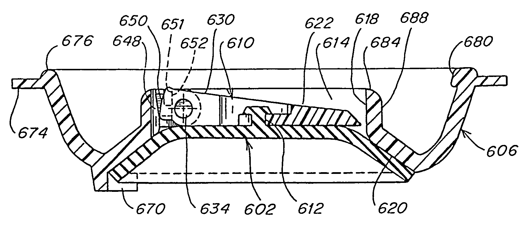
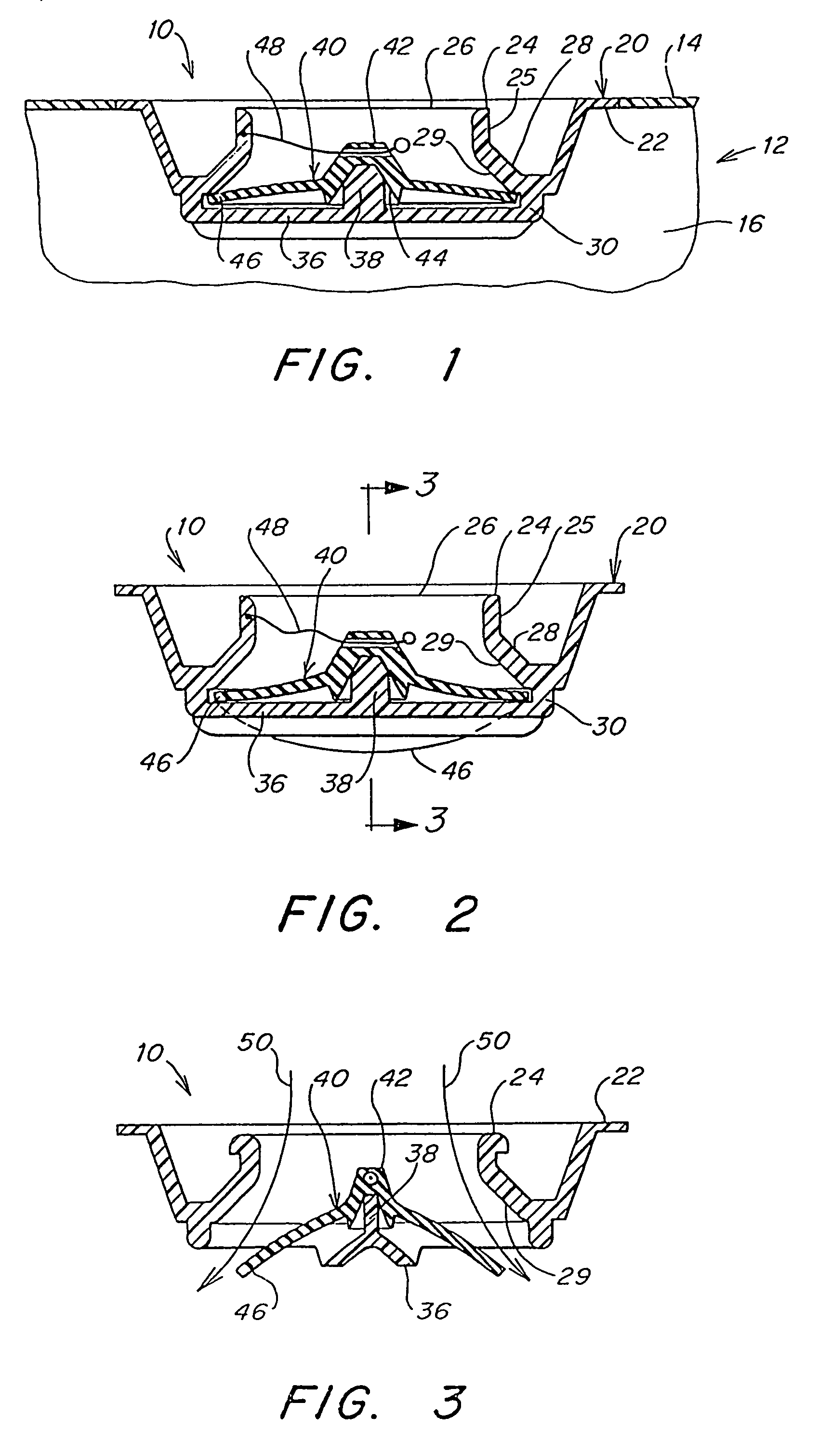
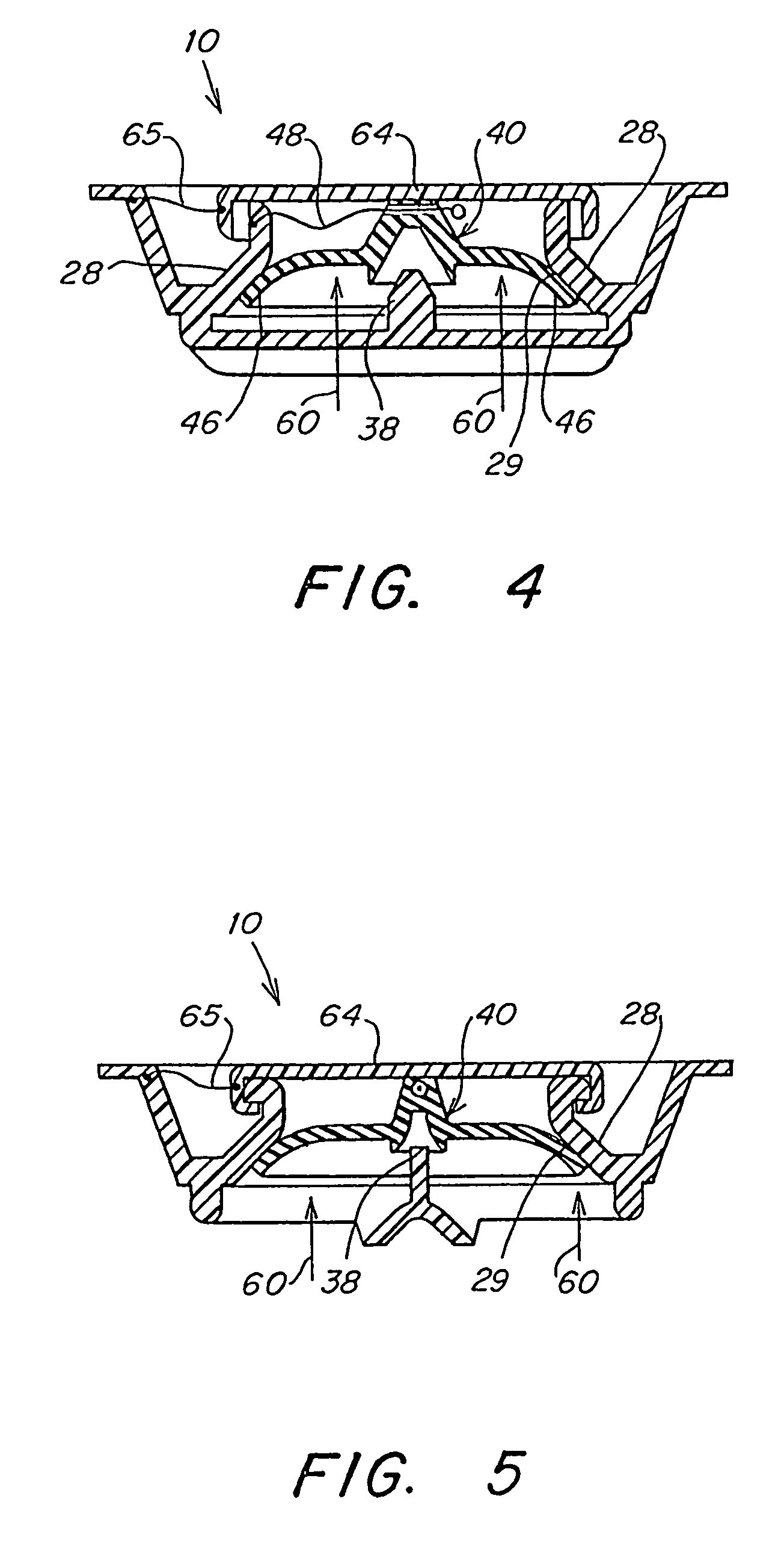
[0062]A self-sealing valve of the present invention can be mounted within an inflatable object such as, for example, an inflatable mattress 12 having a self-sealing valve 10 as illustrated in FIG. 64. The mattress can be inflated, deflated, and a pressure of the mattress can be controlled using any of the self-sealing valves of the present invention disclosed infra. Although in the examples and description of the various embodiments of the self-sealing valve that follow, the description of inflation of the inflatable object refers to the use of air, it is to be appreciated that any suitable fluid may be used for inflation such as, for example, water or nitrogen, and that the use of such fluid with the self-sealing valve of the invention is within the scope of the invention. It is also to be appreciated that although a mattress is illustrated as an inflatable body for which any of the valves of the present invention may be used, the self-sealing valves may be used with any inflatable...


PUM


Abstract

A self-sealing valve comprises a valve housing having a fluid conduit, a valve seat, a flexible diaphragm and a support member. The valve housing is configured to pass fluid through the fluid conduit. The flexible diaphragm provides a self-seal of the fluid conduit, and comprises an area larger than an area of the fluid conduit and a periphery. The support member is configured to retain a portion of a flexible diaphragm. The support member and flexible diaphragm are configured to position the flexible diaphragm against the valve seat to seal the fluid conduit in a closed position of the self-sealing valve, and to facilitate movement of at least a part of the periphery of the flexible diaphragm in a first direction away from the valve seat to an open position.

Description

RELATED APPLICATIONS[0001]This application is a continuation of under 35 U.S.C. § 120 of commonly-owned, U.S. patent application Ser. No. 10 / 328,406, filed Dec. 23, 2002 now U.S. Pat. No. 6,755,208, which is a continuation under 35 U.S.C. § 120 of commonly-owned, U.S. patent application Ser. No. 09 / 867,071, filed May 29, 2001, and issued on Jan. 21, 2003 as U.S. Pat. No. 6,508,264, which is a continuation under 35 U.S.C. §120 of commonly-owned, U.S. patent application Ser. No. 09 / 230,066, filed Jan. 19, 1999, and issued on May 29, 2001 as U.S. Pat. No. 6,237,621, which is a 371 of International Application No. PCT / US97 / 12231, filed Jul. 14, 1997, which claims priority under 35 U.S.C. §119(e) to U.S. Provisional Patent Application Ser. No. 60 / 022,151, filed Jul. 19, 1996, and which are all hereby incorporated by reference in their entirety.FIELD OF THE INVENTION[0002]This invention relates to a self-sealing valve and, more particularly, to any low pressure inflatable device that incl...

Claims


Application Information

Patent Timeline
Patent Type & Authority Patents(United States)
IPC IPC(8): F16K15/18F16K31/44F16K15/20A47C27/08F16K15/03F16K15/14
CPCA47C27/081F16K15/03F16K15/033F16K35/02F16K15/148F16K15/202F16K15/181F16K15/144Y10T137/3584Y10T137/7898Y10T137/789Y10T137/3771Y10T137/374Y10T137/87249F16K15/1821F16K15/1481
Inventor CHAFFEE, ROBERT B.
Owner CHAFFEE ROBERT B
Why Eureka
Try Eureka