Offsetting discharging apparatus with aligning member

a technology of discharging apparatus and aligning member, which is applied in the direction of thin material handling, article separation, stacking articles, etc., can solve the problems of waste of time required to drive the rotating body after moving to the contact position

Inactive Publication Date: 2006-01-17
NISCA KK
View PDF15 Cites 12 Cited by
  • Summary
  • Abstract
  • Description
  • Claims
  • Application Information

AI Technical Summary

Benefits of technology

[0008]This invention provides the rotating bodies for moving the sheets to the alignment reference member for alignment. The rotating bodies are driven in an alignment direction in advance, and touch the sheets being discharged by the discharge means to move the sheets discharged to the storage means toward the alignment reference member. The rotating bodies start an sheet sweeping operation on the sheets being discharged, specifically, without waiting until the sheets are completely discharged, to align them, so compared to the alignment operation in the prior art, there is no wasted time. In other words, because the prior art is configured to move the sheets toward an alignment reference member by touching each sheet with the rotating bodies for alignment after completely discharging the sheets to the storage tray from the discharge means, the time for the aforementioned rotating bodies to move to a position to touch the sheets, and the time required to drive the rotating bodies after moving to the contact position are wasted. In contrast, this invention eliminates that waste of time.
[0010]The rotating bodies can be embodied to be constantly lowered to a predetermined position on the storage tray (an activating position where they can touch the sheets) or they can embodied to switch between the activating position (the position where they can touch the sheets being discharged by the discharge means) and a retracted position (the position where the rotating bodies are separated from the sheets being discharged by the discharge means) so that the rotating bodies are at the activating position only for the necessary amount of time. In either case, it is preferable to drive them in advance in the alignment direction, resulting in a simpler configuration and control.
[0012]The horizontal movement means, in which rotating bodies carry the sheets to a pre-alignment position where the sheets are touched and aligned, has no limitation and can use any known means. However, the offset means for offsetting the position of the sheets being discharged to the storage means relative to the rotating bodies can be shared, thereby eliminating the need for any particular dedicated movement means to be disposed and enabling the sheet discharge apparatus to be compact.
[0018]There are two methods to absorb this offsetting, namely varying the startup timing and the drive speed of the offset means.
[0031]The ninth aspect comprises a function for the control means to quicken the timing to start the aforementioned offset means or to increase the drive speed of the aforementioned offset means when number of sheets is lower than when the number of sheets is higher in the sheet discharge apparatus of the eighth aspect.
[0038]However, as with the eleven aspect of the invention, a structure to enable the rotating bodies to switch between the retracted position and the activating position eliminates the problem of the sheets being arranged obliquely.

Problems solved by technology

In other words, because the prior art is configured to move the sheets toward an alignment reference member by touching each sheet with the rotating bodies for alignment after completely discharging the sheets to the storage tray from the discharge means, the time for the aforementioned rotating bodies to move to a position to touch the sheets, and the time required to drive the rotating bodies after moving to the contact position are wasted.

Method used


Image

  • Offsetting discharging apparatus with aligning member
  • Offsetting discharging apparatus with aligning member
  • Offsetting discharging apparatus with aligning member

Examples


Embodiment Construction

[0088]The following describes in detail the preferred embodiments according to the present invention in reference to the drawings provided.

[0089]A. Mounting Structure and Transport System (FIG. 1)

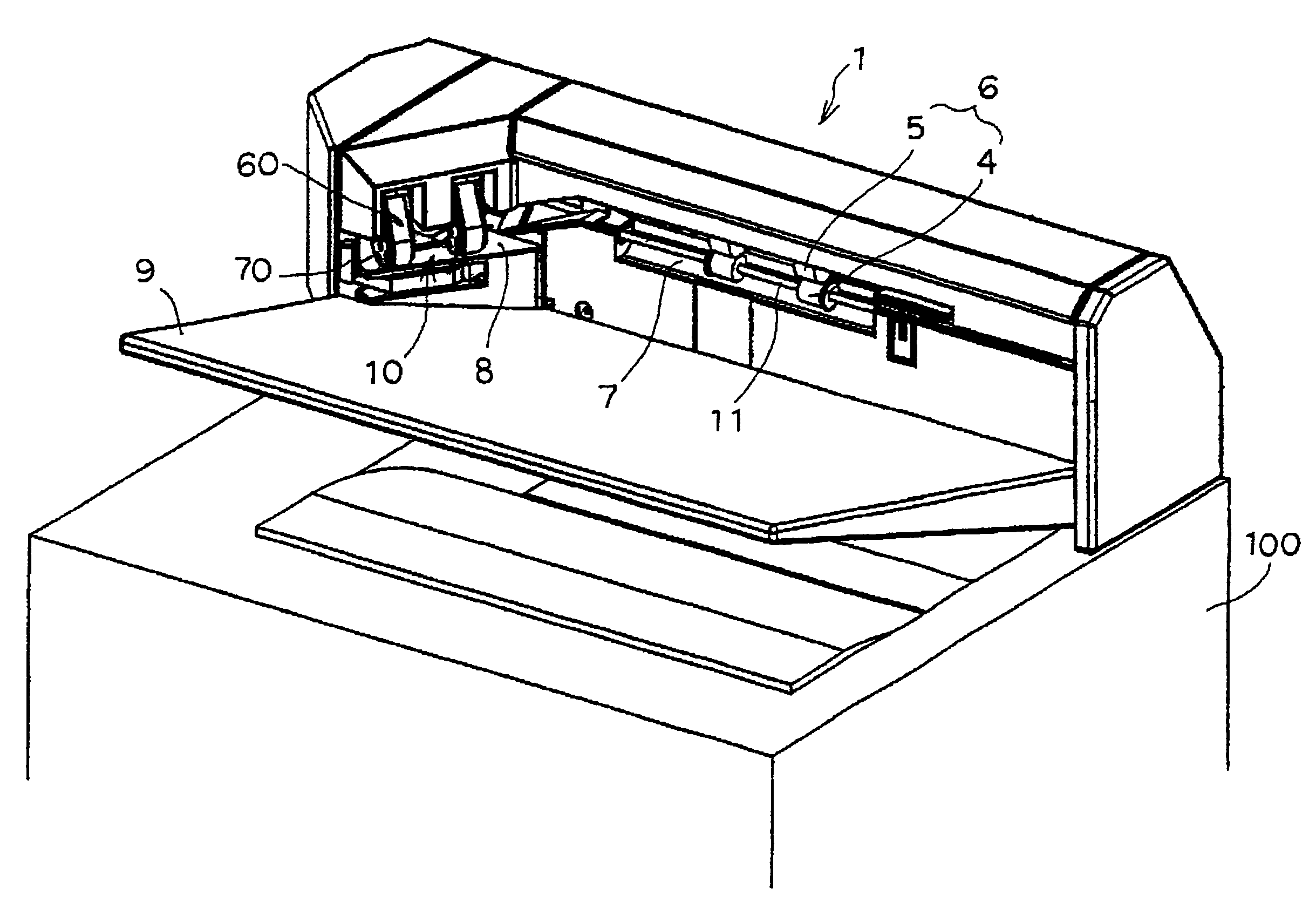
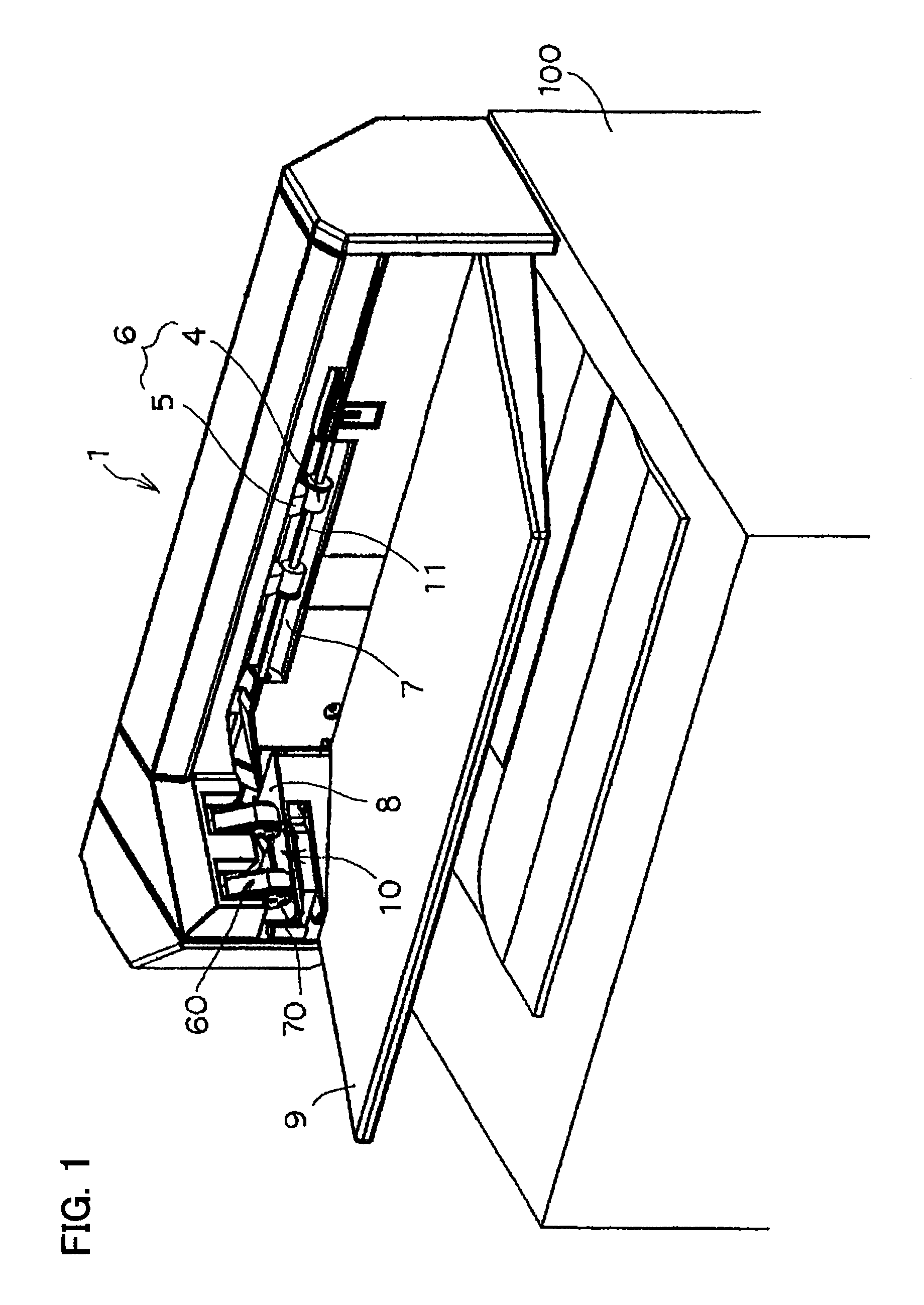
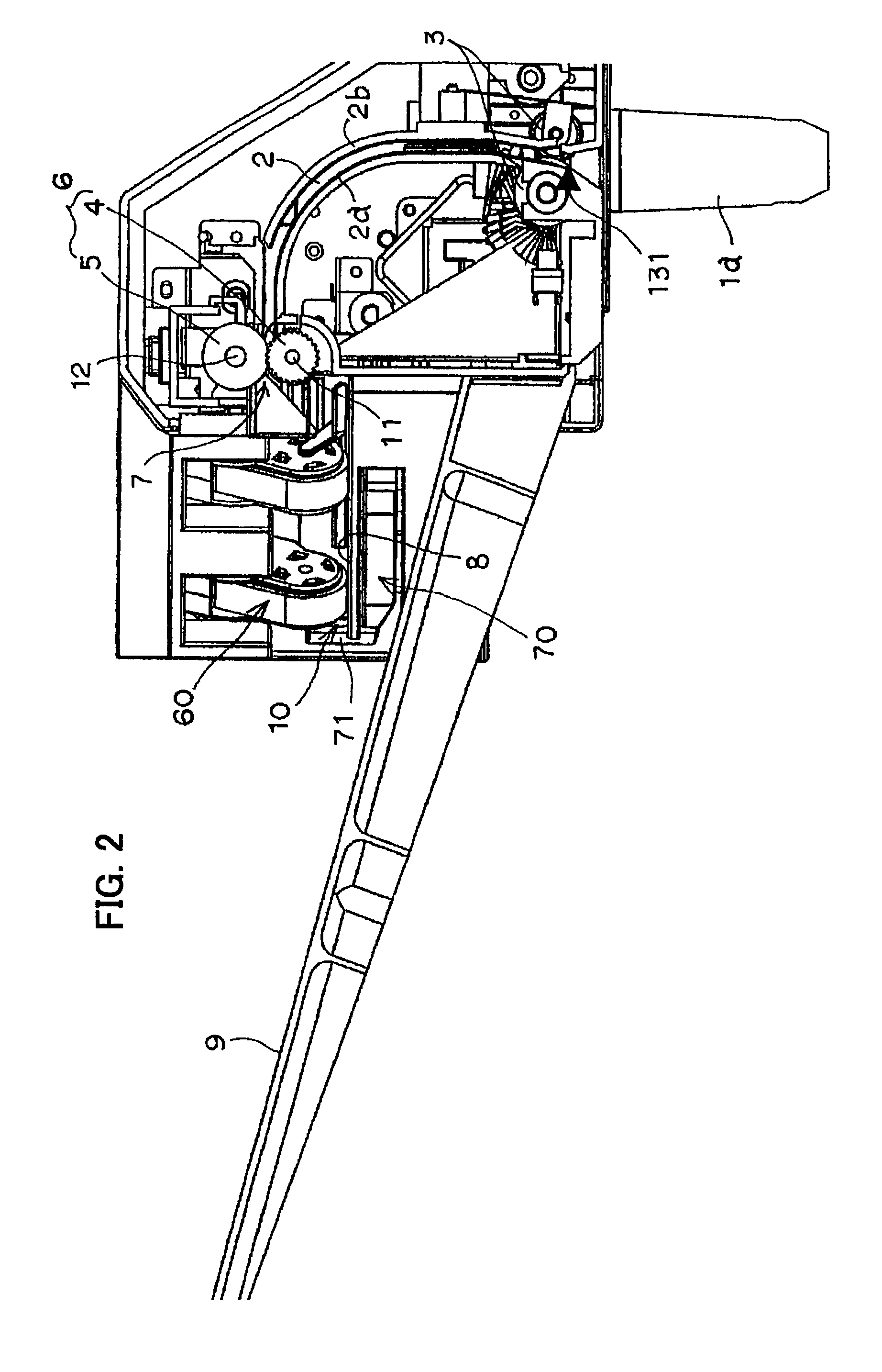
[0090]FIG. 1 shows one embodiment of the image forming apparatus provided with the sheet discharge apparatus according to the present invention. In this embodiment, the sheet discharge apparatus 1 according to the present invention is structured to be detachably mounted to the top of the image forming apparatus 100 comprising a page printer. More specifically, to connect the sheet discharge apparatus 1 and the image forming apparatus 100, a lock arm 1a (FIG. 2) is protrudingly established on the lower side of the sheet discharge apparatus 1, the lock arm mating with a holding portion (not shown in the drawings) inside of the image forming apparatus 100 to mount the sheet discharge apparatus 1 on the top of the image forming apparatus 100.

[0091]Note that although in this embodiment, the imag...


PUM

PropertyMeasurementUnit
sizeaaaaaaaaaa
drive speedaaaaaaaaaa
timeaaaaaaaaaa

Abstract

An offsetting discharging apparatus with aligning member or a sheet discharge apparatus is provided with a sheet discharge device for discharging sheets, a storage device for receiving the sheets discharged from the discharge device, and an alignment reference member for aligning at least one edge of the sheets discharged to the storage means. Furthermore, the sheet discharge apparatus includes rotating bodies (belt unit) that contacts the sheets while the sheets are discharged by the discharge device to move the sheets discharged to the storage device to the alignment reference member. The rotating bodies for alignment do not hinder a discharge operation of discharge rollers of the discharge device, thereby fully utilizing a capacity of a sheet storage tray.

Description

BACKGROUND OF THE INVENTION[0001]This invention relates to an offsetting discharging apparatus with aligning member or a sheet discharge apparatus that discharges sheets discharged from an image forming apparatus such as copiers, printers, facsimile machines or a combination of two or more of these, to a storage tray.[0002]Conventionally, sheet discharge apparatuses that are mounted to image forming apparatuses, such as copiers, printers and facsimiles or a combination of two or more of these, and that form aligned sheet bundles urged toward an aligning member such as a side fence by rotating bodies such as rollers, paddles and belts for aligning each sheet fed to a storage tray from the image forming apparatus and for finishing aligned sheet bundles using staples, punching holes or by applying glue, are well known.[0003]These sheet discharge apparatuses, for example a system described in Japanese Patent Publication (Tokkai) No. 228471, are composed to move sheets toward an alignmen...

Claims


Application Information

Patent Timeline
Patent Type & Authority Patents(United States)
IPC IPC(8): B65H31/00B65H31/34B65H33/08
CPCB65H31/34B65H33/08B65H2301/162B65H2701/1322B65H2301/3613B65H2601/523B65H2301/163
Inventor SAITO, TAKASHISASAMOTO, SHINYA
Owner NISCA KK
Why Eureka
Try Eureka