Stabilizer pad configurations

Inactive Publication Date: 2006-01-17
LAGSDIN ANDRY
View PDF51 Cites 15 Cited by
  • Summary
  • Abstract
  • Description
  • Claims
  • Application Information

AI Technical Summary

Benefits of technology

[0014]In yet another further aspect of the invention, the layers of the laminate may not be of all the same height. Rather, they may be stepped in such a manner that the layers adjacent the flaps of the bracket ha

Problems solved by technology

The first surface is unsuitable for contact with a hard surface, since the grouser points could damage or mar the hard asphalt or concrete.
While such prior a

Method used


Image

  • Stabilizer pad configurations
  • Stabilizer pad configurations
  • Stabilizer pad configurations

Examples


Embodiment Construction

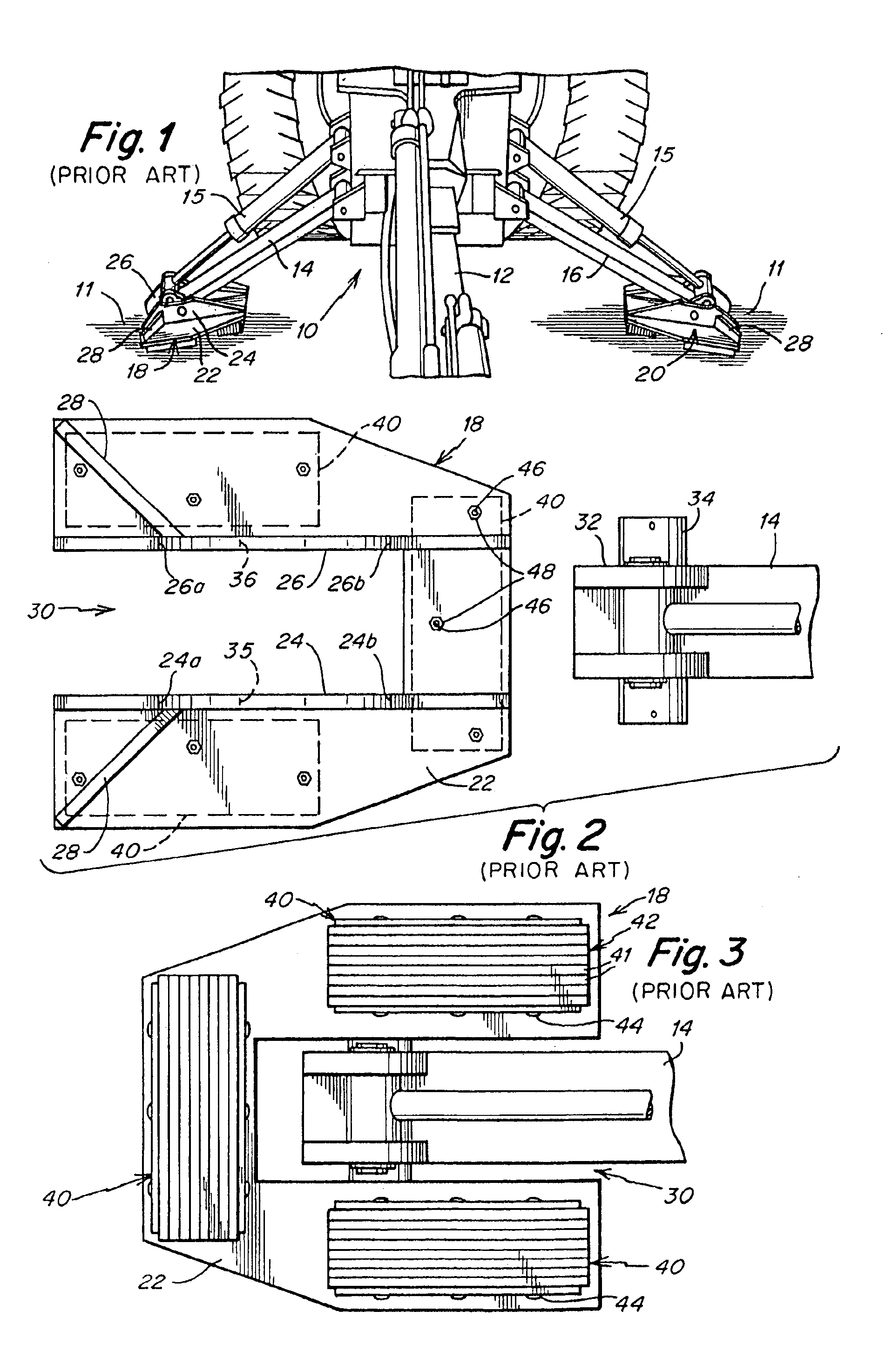
[0067]FIGS. 1-3 illustrate a typical piece of construction equipment or earth-moving apparatus, such as a loader / backhoe 10 with which the stabilizer pad assemblies of this invention are intended to be utilized. Backhoe 10 includes a shovel mechanism 12, stabilizer arms 14 and 16 and associated stabilizer pads 18 and 20 respectively. Hydraulic piston 15 typically operates each stabilizer arm 14 and 16 independently of the other. FIG. 1 illustrates the positions of arms 14 and 16 during operation of the shovel mechanism to provide the desired lateral stability to backhoe 10 to prevent lateral movement of backhoe 10. As can be seen, arms 14 and 16 are disposed on opposite sides of backhoe 10 adjacent shovel mechanism 12. Each arm 14 and 16 extends from backhoe 10 to form an acute angle with respect to an underlying surface 11 upon which backhoe 10 and arms 14 and 16 rest. Surface 11 typically could be formed of soil, rock, asphalt, gravel or concrete, although backhoe 10 may be used i...


PUM


Abstract

Pad assemblies configured to be used in conjunction with stabilizer pads mounted onto stabilizer arms used to stabilize earth moving and other construction equipment. The pad assemblies are formed from either a resilient laminate or solid piece mounted onto a bracket which in turn is mounted onto the stabilizer pad. The pad assemble includes a support bracket, and a pad having a base captured in the support bracket and formed of a resilient material that defines a base surface. The pad is being retained by said support bracket and has a ground engaging surface opposite to the base surface and defined as an uneven ground engaging surface formed of separate ground engaging pad surface areas that terminate at different distances from the base surface.

Description

RELATED APPLICATIONS[0001]This application is a continuation-in-part of application Ser. No. 09 / 575,931 filed May 23, 2000, now U.S. Pat. No. 6,471,246, which, in turn, is a continuation of application Ser. No. 09 / 070,638 filed Apr. 30, 1998, now U.S. Pat. No. 6,109,650. The applicant hereby makes a claim to priority to both of the above applications. Furthermore, the above applications as well as U.S. Pat. Nos. 4,761,021; 5,050,904; 5,054,812; 4,889,362; 5,564,871; 5,466,004; 5,547,220; 5,667,245; 5,992,883; 5,957,496; 6,109,650; 6,270,119; 6,422,603 are all hereby incorporated by reference in their entirety.FIELD OF THE INVENTION[0002]This invention relates generally to stabilizer pads for vehicles, and more particularly to improved stabilizer pad configurations which can be used in conjunction with a pivotally mounted, two-way stabilizer pads.BACKGROUND OF THE INVENTION[0003]Construction equipment, such as earth-moving vehicles and the like, must be stabilized during construction...

Claims


Application Information

Patent Timeline
IPC IPC(8): B60S9/02B60S9/10E02F9/08
CPCB60S9/02E02F9/085B60S9/10
Inventor LAGSDIN, ANDRY
Owner LAGSDIN ANDRY
Why Eureka
Try Eureka