Graphic user interface having touch detectability

a user interface and touch detection technology, applied in the field of control panels, can solve problems such as the difficulty of recognizing the markings on the display of the remote control uni

Active Publication Date: 2006-01-17
KONINKLIJKE PHILIPS ELECTRONICS NV
View PDF11 Cites 65 Cited by
  • Summary
  • Abstract
  • Description
  • Claims
  • Application Information

AI Technical Summary

Benefits of technology

[0012]It is an object of the invention to provide a control panel for an electrical / electronic device which allows a user to use the control panel without looking at the control panel.

Problems solved by technology

However, as the user acquires more and more devices, these remote control units start to accumulate leaving an array of remote control units on the user's coffee table with the problem of selecting the appropriate remote control unit for controlling the desired device.
However, one problem with these types of remote control units is that it is necessary for the user to look at the remote control unit in order to operate it.
As such, it is then difficult to discern the markings on the display of the remote control unit.

Method used


Image

  • Graphic user interface having touch detectability
  • Graphic user interface having touch detectability
  • Graphic user interface having touch detectability

Examples


Embodiment Construction

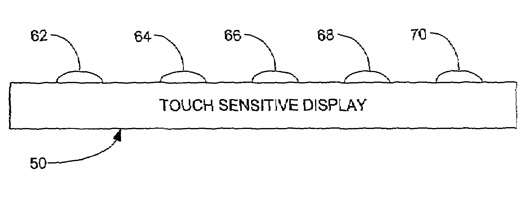
[0026]FIG. 3 shows the GUI 50 of a remote control unit incorporating the subject invention. The GUI includes three regions, an information section 52 which includes information for the selected device, a device selection section 54 for displaying control icons for selecting the desired device, e.g., TV 58 and LD (laser disc) 60, and a control function section 56 for displaying control icons for controlling the desired device, in this case, numbers 1–0 icons 61–70.

[0027]FIG. 4 shows an edge view of the GUI 50 where it will be apparent that surface of the GUI in the vicinity of the icons 62, 64, 66, 68 and 70 is raised. It should be understood that while FIG. 4 only shows some of the icons being raised, the surface of the GUI in the vicinity of other icons, including 58, 60, 61, 63, 65, 67 and 69, may also be raised.

[0028]Once a user of the remote control unit 50 is familiar with the layout of the control icons, the user is then able to select the appropriate icon by merely sliding hi...


PUM


Abstract

A control panel for an electrical/electronic device allows a user to use the control panel without looking at the control panel. The control panel is formed by a graphic user interface (GUI) having a display for displaying various control icons for controlling the device. The display is touch sensitive so that a user is able to select the control function by pressing on the appropriate control icon. The display further has touch detectability for enabling a user to distinguish between the icons by touch. The touch detectability may be in the form of the surface of the display having raised portion in the vicinity of the control icons. While the positioning of the raised portions may be fixed, to allow for changing layouts of the control icons, the display may be flexible and an array of actuators may underlie the display whereby the actuators are selectively activated to press against the underside of the display thereby raising the upper surface of the display in the vicinities of the control icons.

Description

BACKGROUND OF THE INVENTION[0001]1. Field of the Invention[0002]The subject invention relates to control panels having a flat panel graphic user interface (GUI). The invention further relates to a remote control having such a control panel.[0003]2. Description of the Related Art[0004]Consumer electronics devices are often provided with remote control units for controlling the device from the comfort of one's easy chair. These remote control units typically are rectangular in shape and carry a plurality of buttons for operating the various control functions of the electronic devices.[0005]However, as the user acquires more and more devices, these remote control units start to accumulate leaving an array of remote control units on the user's coffee table with the problem of selecting the appropriate remote control unit for controlling the desired device.[0006]This problem has been addressed with universal remote control units which either include or may be programmed with the codes fo...

Claims


Application Information

Patent Timeline
Patent Type & Authority Patents(United States)
IPC IPC(8): G06F13/00G06F3/041G06F1/16G06F3/00G06F3/01G06F3/048H04Q9/00
CPCG06F1/1626G06F3/016G06F3/04886G06F3/041H03J2200/26G06F2203/04809
Inventor JANEVSKI, ANGEL
Owner KONINKLIJKE PHILIPS ELECTRONICS NV
Why Eureka
Try Eureka