Method and apparatus for flexible fluid delivery for cooling desired hot spots in a heat producing device

a heat producing device and fluid delivery technology, applied in the direction of power cables, semiconductor/solid-state device details, cables, etc., can solve the problems of not being able to provide more fluid to the hotter areas, the design of the hot spot is not good, and the microchannels including conventional parallel channel arrangements used are not well suited to cooling the heat producing devi

Inactive Publication Date: 2006-01-24
VERTIV CORP
View PDF161 Cites 158 Cited by
  • Summary
  • Abstract
  • Description
  • Claims
  • Application Information

AI Technical Summary

Benefits of technology

[0010]In yet another aspect of the invention, a method of manufacturing a heat exchanger is configured to cool a heat source. The method comprises forming an interface layer that is configurable to be coupled to the heat source. The interface layer has a thermal conductivity of at least 20 W/m-K to sufficiently transfer heat between the heat source and the interface layer. The method also comprises forming a manifold layer in conjunction with the interface layer, wherein the manifold layer is configured to provide fluid to flow along the interface layer to cool the heat source. The method further comprises determining one or more hot spot locations in the heat source. The method further comprises configuring the heat exchanger into a plurality of interface hot spot regions, wherein each interface hot spot region is associated with the one or more hot spot locations. The method further comprises coupling a plurality of fluid ports to the heat exchanger, wherein one or more of the plurality of fluid ports are configured to circulate fluid directly to one or more selected interface hot spot regions in the plurality of interface hot spot regions. A portion of the

Problems solved by technology

However, existing microchannels include conventional parallel channel arrangements which are used are not well suited for cooling heat producing devices which have spatially-varying heat loads.
The large pressure drop formed in the heat exchanger 10 makes pumping fluid to the heat exchange

Method used


Image

  • Method and apparatus for flexible fluid delivery for cooling desired hot spots in a heat producing device
  • Method and apparatus for flexible fluid delivery for cooling desired hot spots in a heat producing device
  • Method and apparatus for flexible fluid delivery for cooling desired hot spots in a heat producing device

Examples


Embodiment Construction

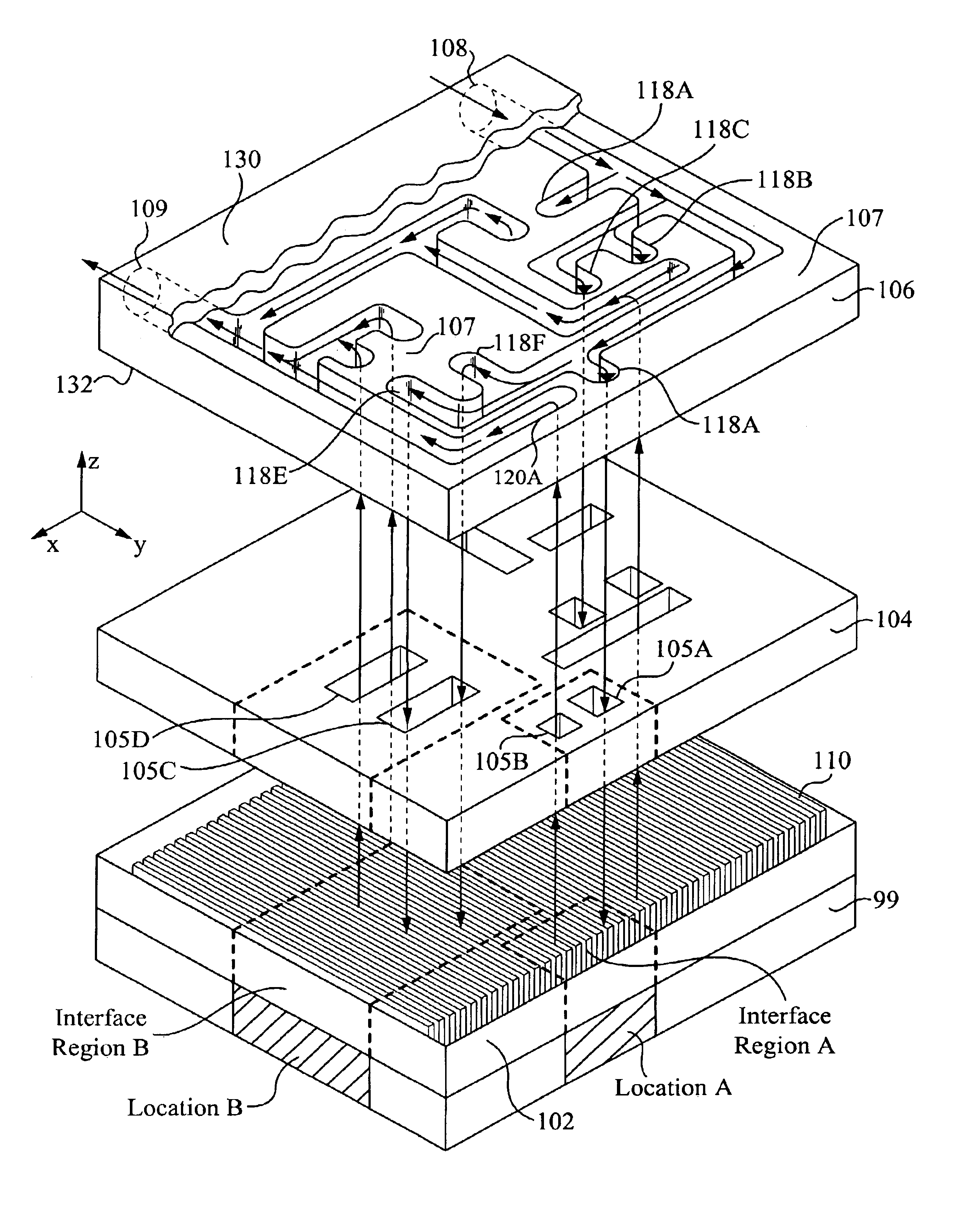
[0038]Generally, the heat exchanger captures thermal energy generated from a heat source by passing fluid through selective areas of the interface layer which is preferably coupled to the heat source. In particular, the fluid is directed to specific areas in the interface layer to cool the hot spots and areas around the hot spots to generally create temperature uniformity across the heat source while maintaining a small pressure drop within the heat exchanger. As discussed in the different embodiments below, the heat exchanger utilizes a plurality of apertures, channels and / or fingers in the manifold layer as well as conduits in the intermediate layer to direct and circulate fluid to and from selected hot spot areas in the interface layer. Alternatively, the heat exchanger includes several ports which are specifically disposed in predetermined locations to directly deliver fluid to and remove fluid from the hot spots to effectively cool the heat source.

[0039]It is apparent to one sk...


PUM

PropertyMeasurementUnit
Poweraaaaaaaaaa
Poweraaaaaaaaaa
Temperatureaaaaaaaaaa

Abstract

A heat exchanger apparatus and method of manufacturing comprising: an interface layer for cooling a heat source and configured to pass fluid therethrough, the interface layer having an appropriate thermal conductivity and a manifold layer for providing fluid to the interface layer, wherein the manifold layer is configured to achieve temperature uniformity in the heat source preferably by cooling interface hot spot regions. A plurality of fluid ports are configured to the heat exchanger such as an inlet port and outlet port, whereby the fluid ports are configured vertically and horizontally. The manifold layer circulates fluid to a predetermined interface hot spot region in the interface layer, wherein the interface hot spot region is associated with the hot spot. The heat exchanger preferably includes an intermediate layer positioned between the interface and manifold layers and optimally channels fluid to the interface hot spot region.

Description

RELATED APPLICATIONS[0001]This Patent Application claims priority under 35 U.S.C. 119 (e) of the co-pending U.S. Provisional Patent Application, Ser. No. 60 / 423,009, filed Nov. 1, 2002 and entitled “METHODS FOR FLEXIBLE FLUID DELIVERY AND HOTSPOT COOLING BY MICROCHANNEL HEAT SINKS” which is hereby incorporated by reference. This Patent Application also claims priority under 35 U.S.C. 119 (e) of the co-pending U.S. Provisional Patent Application, Ser. No. 60 / 442,383, filed Jan. 23, 2003 and entitled “OPTIMIZED PLATE FIN HEAT EXCHANGER FOR CPU COOLING” which is also hereby incorporated by reference. In addition, this Patent Application claims priority under 35 U.S.C. 119 (e) of the co-pending U.S. Provisional Patent Application, Ser. No. 60 / 455,729, filed Mar. 17, 2003 and entitled “MICROCHANNEL HEAT EXCHANGER APPARATUS WITH POROUS CONFIGURATION AND METHOD OF MANUFACTURING THEREOF”, which is hereby incorporated by reference.FIELD OF THE INVENTION[0002]The invention relates to a method...

Claims


Application Information

Patent Timeline
IPC IPC(8): F28F7/00F04B17/00F04B19/00F28D15/02F28F3/12G06Q20/20H01L23/473H04L29/06
CPCF04B17/00F04B19/006F28D15/0266F28F3/12F28F13/06G06Q20/20H01L23/473F28D21/0015Y10T29/4935F28F2260/02H01L2924/0002F28F2210/10H01L2924/00
Inventor KENNY, THOMAS W.MUNCH, MARKZHOU, PENGSHOOK, JAMES GILLUPADHYA, GIRISHGOODSON, KENNETHCORBIN, DAVID
Owner VERTIV CORP
Why Eureka
Try Eureka