Method for mapping heart electrophysiology

a technology of electrophysiology and mapping method, which is applied in the field of electrophysiology equipment, can solve the problems of not providing a high resolution view, affecting the collection of diagnostic information, and injuring the hear

Inactive Publication Date: 2006-01-24
ST JUDE MEDICAL ATRIAL FIBRILLATION DIV
View PDF3 Cites 492 Cited by
  • Summary
  • Abstract
  • Description
  • Claims
  • Application Information

AI Technical Summary

Benefits of technology

[0005]The electrophysiology apparatus of the invention is partitioned into several interconnected subsystems. The measurement catheter system introduces a modulated electric field into the heart chamber. The blood volume and the moving heart wall surface modify the applied electric field. Electrode sites within the heart chamber passively monitor the modifications to the field and a dynamic representation of the location of the interior wall of the heart is developed for display to the physician. Electrophysiologic signals generated by the heart itself are also measured at electrode sites within the heart and these signals are low pass filtered and displayed along with the dynamic wall representation. This composite dynamic electrophysiologic map may be displayed and used to diagnose the underlying arrhythmia.

Problems solved by technology

There are numerous problems associated with these electrophysidlogic diagnostic and therapeutic procedures.
The motion of the diagnostic catheter and treatment catheter can injure the heart and provoke bouts of arrhythmia which interfere with the collection of diagnostic information.
In addition, the traditional mapping techniques do not provide a high resolution view of the electrical activity of the heart which makes it difficult to precisely locate the source of the arrhythmia.

Method used


Image

  • Method for mapping heart electrophysiology
  • Method for mapping heart electrophysiology
  • Method for mapping heart electrophysiology

Examples


Embodiment Construction

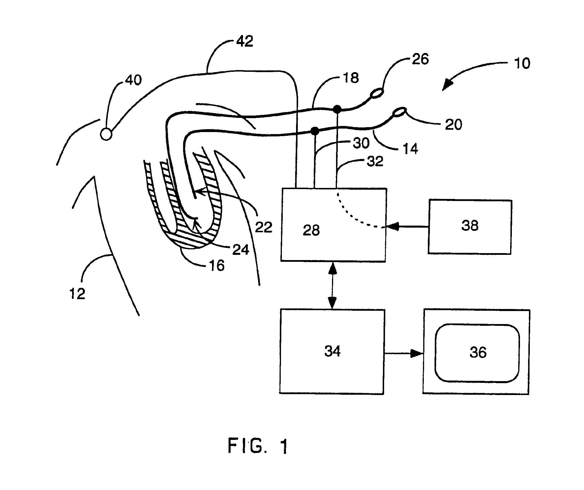
[0031]FIG. 1 shows the electrophysiologic apparatus 10 connected to a patient 12. In a typical procedure a monitoring catheter system 14 is placed in the heart 16 to generate a display of the electrical activity of the heart 16. After diagnosis a therapy catheter 18 may be inserted into the heart to perform ablation or other corrective treatment.

[0032]The monitoring catheter 14 has a proximal end 20 which may be manipulated by the attending physician, and a distal end 22 which carries a monitoring catheter electrode set 44. In general the distal end 22 of the monitoring catheter 14 will be relatively small and will float freely in the heart chamber. The therapy catheter 18 has a distal end 24 which carries a therapy catheter electrode set 46. The therapy catheter also has proximal end 26 which can be manipulated by the attending physician.

[0033]The electrode sets located on the catheters are coupled to an interface system 28, through appropriate cables. The cable 30 connects the mon...


PUM

PropertyMeasurementUnit
DAaaaaaaaaaa
frequencyaaaaaaaaaa
frequencyaaaaaaaaaa

Abstract

A mapping catheter is positioned in a heart chamber, and active electrode sites are activated to impose an electric field within the chamber. The blood volume and wall motion modulates the electric field, which is detected by passive electrode sites on the preferred catheter. Electrophysiology measurements, as well as geometry measurements, are taken from the passive electrodes and used to display a map of intrinsic heart activity.

Description

CROSS REFERENCED TO RELATED CASES[0001]This application is a continuation of Ser. No. 09 / 005,105, filed Jan. 9, 1998, now abandoned, which is a continuation-in-part of Ser. No. 08 / 387,832, filed May 26, 1995, now U.S. Pat. No. 6,240,307, which is a national stage application of PCT / US93 / 09015, filed Sep. 23, 1993, which in turn claims priority from U.S. Ser. No. 07 / 950,448, filed Sep. 23, 1992, now U.S. Pat. No. 5,297,549 and U.S. Ser. No. 07 / 949,690, filed September 23, 1992, now U.S. Pat. No. 5,311,866.FIELD OF THE INVENTION[0002]The parent invention relates to electrophysiology apparatus which is used to measure and to visualize electrical activity occurring in a patient's heart. The system can display both a visual map of the underlying electrical activity originating in a chamber of a patient's heart and the location of a therapy catheter located within a heart chamber. The electrophysiology apparatus includes several subsystems including: a therapy catheter system, a measureme...

Claims


Application Information

Patent Timeline
Patent Type & Authority Patents(United States)
IPC IPC(8): A61B5/04A61B5/05A61B5/107A61B5/296A61B5/308A61B18/14A61B18/18A61B18/24A61M25/00A61N1/362A61N1/37
CPCA61B5/04085A61B5/0422A61B5/0538A61B5/1076A61B5/6853A61B5/6858A61B18/1492A61N1/3625A61N1/3702A61B5/042Y10T29/49117A61B5/0428A61B18/18A61B18/1815A61B18/24A61B2018/00214A61B2018/00267A61B2018/00839A61B2560/045A61B2562/0209A61B2562/043A61B2562/046A61B2018/00577A61B2018/00351A61B2018/0022A61B2018/00892A61B2018/00875A61B2090/061A61B5/282A61B5/283A61B5/287A61B5/30
Inventor BEATTY, GRAYDON ERNESTBUDD, JEFFREY ROBERTHAUCK, JOHN ANDERSON
Owner ST JUDE MEDICAL ATRIAL FIBRILLATION DIV
Why Eureka
Try Eureka