Tactile sensing method and system

Active Publication Date: 2006-01-24
HARMONIC DRIVE SYST IND CO LTD
View PDF4 Cites 17 Cited by
  • Summary
  • Abstract
  • Description
  • Claims
  • Application Information

AI Technical Summary

Benefits of technology

[0022]the controller including an A/D converter for A/D conversion of the sum output supplied via the signal output line, an analyzer that, from the sum output converted by the A/D converter, of the touch force and touch direction acting on each measurement point, utilizes trigonometric function orthogonality to obtain at least the touch force acting on each measurement point, an automatic gain control circuit that compares voltage amplitude measured at each measurement point to a reference voltage preset for each measurement point and adjusts the voltage amplitude of each sine wave signal frequency applied to each sensor unit of the touch sensor to reduce any difference between the measured and reference voltages, and a D/A converter that generates and outputs a composite sine wave that includes sine wave signals of each frequency with the voltage amplitude thus adjusted.
[0023]In accordance with the present in

Problems solved by technology

A drawback of these touch sensors is that it requires many wires to read the information at the measurement points.
A problem with conventional touch sensors is that sensor resolution is degraded by an input of a strong signal exceeding a prescribed level, w

Method used


Image

  • Tactile sensing method and system
  • Tactile sensing method and system
  • Tactile sensing method and system

Examples


examples

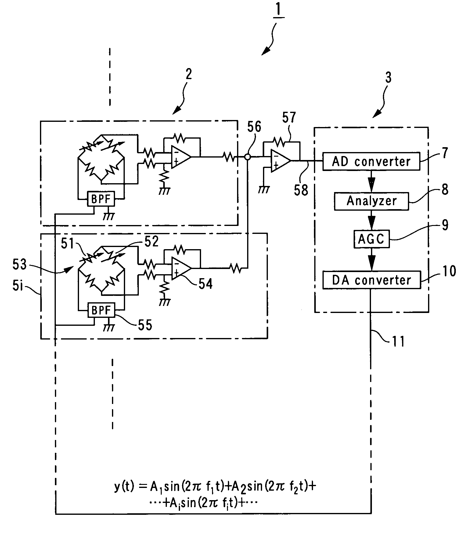
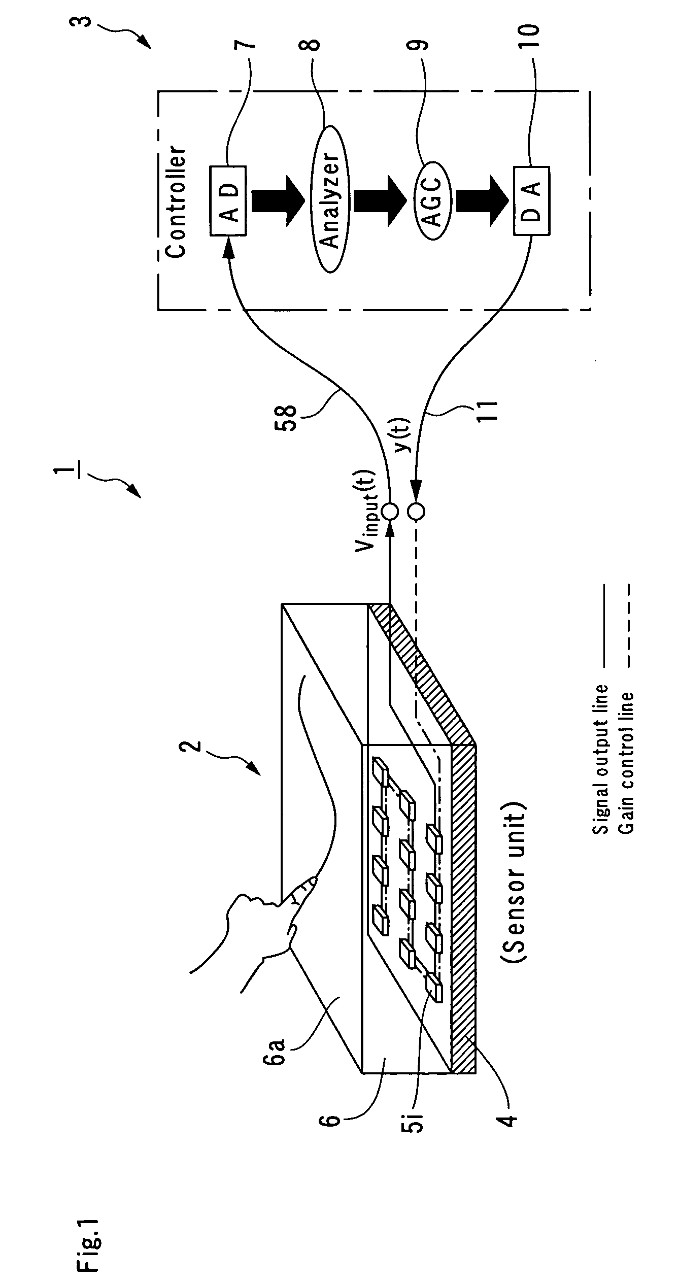
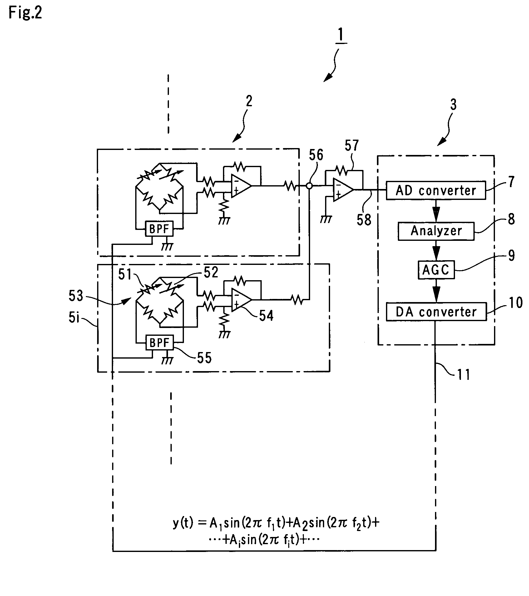
[0064]As shown in FIG. 8, a touch sensor 2 was fabricated by forming 1 mm cuts in a steel plate 21 to form a plurality of regions, in each of which a sensor unit 5 is located. Each sensor unit 5 included a bridge circuit 53 comprised of two strain gauges 51 and 52 adhered to a measurement point. An output of the bridge circuit 53 was temperature-compensated. A software-generated composite sine wave y(t) from a D / A converter 10 of a controller 3 was updated by a 30 kHz analogue output. Via analogue BPF 55, a single sine wave was applied to the bridge circuit 53 at each measurement point, and a secondary bi-cut type BPF 55 was used that was able to increase a quality factor to apply only a single sine wave to the bridge circuit 53. Regarding the BPF 55, due to device element variation, it is difficult to accurately align a center frequency with a set value, so a frequency of the sine wave output by the D / A converter 10 was aligned with the center frequency of the BPF 55. Each analogue...


PUM


Abstract

A system for detecting tactile information includes strain-gauge touch sensors and a controller. Based on the sum output from each of tough-sensor sensor units, an analyzer in the controller calculates touch force Fi(t) at each measurement point. An automatic gain control adjusts the voltage amplitude Ai(t) of a sine wave of frequency fi applied to the sensor units at each measurement point to bring the voltage amplitude measured at each measurement point in line with a target voltage. The adjusted voltage Ai(t) is applied to the bandpass filter with a composite sine wave y(t) which includes sine waves of each frequency corresponding to the adjusted voltage amplitude Ai(t). This makes it possible to reduce the number of lines between the controller and touch sensors that includes numerous measurement points, and enables the gain of the touch sensors constituted by strain gauges to be controlled within an appropriate range.

Description

BACKGROUND OF THE INVENTION[0001]1. Technical Field[0002]The present invention relates to an automatic adjustment type method and system for detecting tactile information in which sensitivity can be automatically adjusted in accordance with outputs of strain gauges constituting sensor elements adhered to measurement locations.[0003]2. Related Art[0004]Human skin has various types of touch receptors that enable it to distinguish touches ranging from light touches to impact forces. There are approximately 1500 Meissner's tactile corpuscles and 750 Merkel's tactile disks per square centimeter in the upper part of the skin of the fingertip, and some 75 Pacinian corpuscles and Ruffini endorgans per square centimeter. These four types of touch receptors, with their different time and spatial responses, provide a broad measuring range.[0005]In an environment in which people and robots coexist, it is considered that the robots would have to be equipped with touch sensors that continuously m...

Claims


Application Information

Patent Timeline
IPC IPC(8): H04B15/00G01L1/00G01L1/20G01L1/22G01L5/00G01L5/22G09G5/00
CPCG01L1/205G01L5/228G01L5/009G01L1/2256
Inventor KANEKO, MAKOTOHORIE, RYUTA
Owner HARMONIC DRIVE SYST IND CO LTD
Why Eureka
Try Eureka