Transflective liquid crystal display

Active Publication Date: 2005-08-04
INNOLUX CORP
View PDF2 Cites 13 Cited by
  • Summary
  • Abstract
  • Description
  • Claims
  • Application Information

AI Technical Summary

Benefits of technology

[0009] One aspect of the present invention is to provide a layout pattern for pixel electrode layers of a transflective LCD device in order to adj

Problems solved by technology

The transmissive type LCD device uses a backlight module, in which incident light is absorbed, or passes through the LC layer, resulting in the disadvantages of faded color and reduced contrast ratio under a natural light sourc

Method used


Image

  • Transflective liquid crystal display
  • Transflective liquid crystal display
  • Transflective liquid crystal display

Examples


Example

First Embodiment

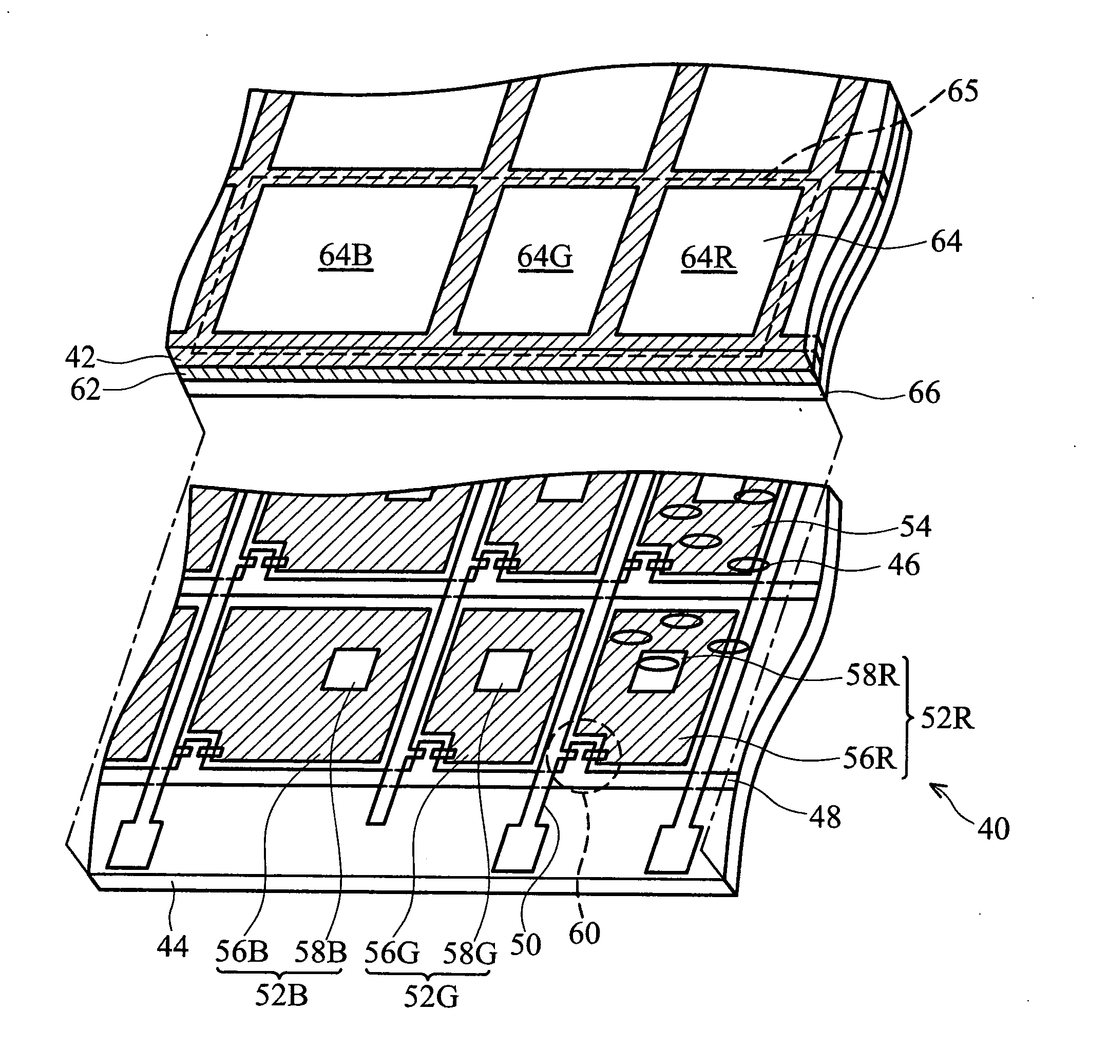
[0019] The present invention modifies RGB pixel electrode layers to obtain different sizes of RGB reflective regions on the condition that the RGB pixel electrode layers have identical transmissive regions.

[0020]FIG. 2 is an exploded diagram of a transflective LCD device according to the first embodiment of the present invention. A transflective LCD device 40 comprises an upper substrate 42, a lower substrate 44 and a liquid crystal layer 46 formed in a space between the upper substrate 42 and the lower substrate 44. On the inner surface of the lower substrate 44, a plurality of gate lines 48 extending in a traverse direction and a plurality of data lines 50 extending in a lengthwise direction intersect to define an array of pixel areas 54. Each pixel area 54 comprises a pixel electrode region 52 and a TFT device 60 electrically connected to each other. The pixel electrode region 52 has a reflective region 56 and a transmissive region 58. The TFT device 60 is fabri...

Example

Second Embodiment

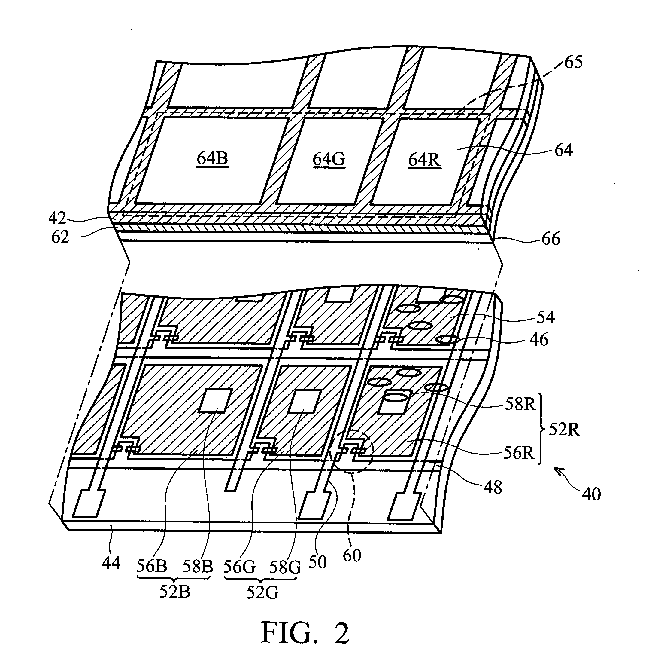
[0027] Based on the size design rules described in the first embodiment, the present invention further provides a transparent region (or an opening) in the red element 64R, the green element 64G or the blue element 64B. Additionally, the projection of the transparent region onto the lower substrate 44 is within the corresponding reflective region 56. Cooperating with backlight source adjustment, a reflective light passing through the transparent region in reflective mode displays a non-colored light, thus increasing brightness and aiding white point adjustment in reflective mode.

[0028]FIG. 3A is an exploded diagram of color elements and pixel electrode regions according to the second embodiment of the present invention. The color elements 64R, 64G and 64B and pixel electrode regions 52R, 52G and 52B in the second embodiment are substantially similar to those of the first embodiment, with the similar portions omitted herein. The green element 64G has a transparent ...


PUM


Abstract

A transflective liquid crystal display has a plurality of pixel electrode layers corresponding to a plurality of color elements. A first pixel electrode layer has a first reflective region and a first transmissive region. A second pixel electrode layer has a second reflective region and a second transmissive region. A third pixel electrode layer has a third reflective region and a third transmissive region. The first reflective region is larger than the second reflective region, and the first reflective region is larger than the third reflective region.

Description

BACKGROUND OF THE INVENTION [0001] 1. Field of the Invention [0002] The invention relates to a transflective liquid crystal display and more particularly to the structuring of a reflective layer in the transflective LCD device to adjust chromatic properties between a reflective region and a transmissive region. [0003] 2. Description of the Related Art [0004] Liquid crystal display (LCD) devices are typically classified as transmissive and reflective types according to the light source. The transmissive type LCD device uses a backlight module, in which incident light is absorbed, or passes through the LC layer, resulting in the disadvantages of faded color and reduced contrast ratio under a natural light source or an artificial exterior light source. Conversely, the reflective type LCD device uses ambient incident light from an exterior light source, resulting in superior performance and high contrast ratio under outdoor sunlight. Additionally, because of its low power consumption, t...

Claims


Application Information

Patent Timeline
IPC IPC(8): G02F1/133G02F1/1335G02F1/1343
CPCG02F2201/52G02F1/133555
Inventor CHUANG, LI-SENCHANG, WEI-CHIHTSAI, CHIA-YIWEN, CHI-JAIN
Owner INNOLUX CORP
Why Eureka
Try Eureka