Hydraulic excavator

Active Publication Date: 2014-10-30
KOMATSU LTD
View PDF34 Cites 17 Cited by
  • Summary
  • Abstract
  • Description
  • Claims
  • Application Information

AI Technical Summary

Benefits of technology

[0030]In the hydraulic excavator according to the tenth aspect, the reducing agent hose is arranged along the center frame. As a result, it is possible to protect the reducing agent hose.
[0031]In the hydraulic excavator according to the eleventh aspect, the reducing agent hose is supported by the first column member via the support member. Accordingly, the reducing agent pump and the reducin

Problems solved by technology

As a result, accessing the reducing agent pump is not easy.
In addition, when the fuel tank is arranged on the outer side of the reducing agent pump, the fuel tank is an obstacle when accessing the reducing agent pump.
As a result, maintenance work on the reducing agent pump is complicated.
As a result, when accessing the fuel filter an

Method used


Image

  • Hydraulic excavator
  • Hydraulic excavator
  • Hydraulic excavator

Examples


Example

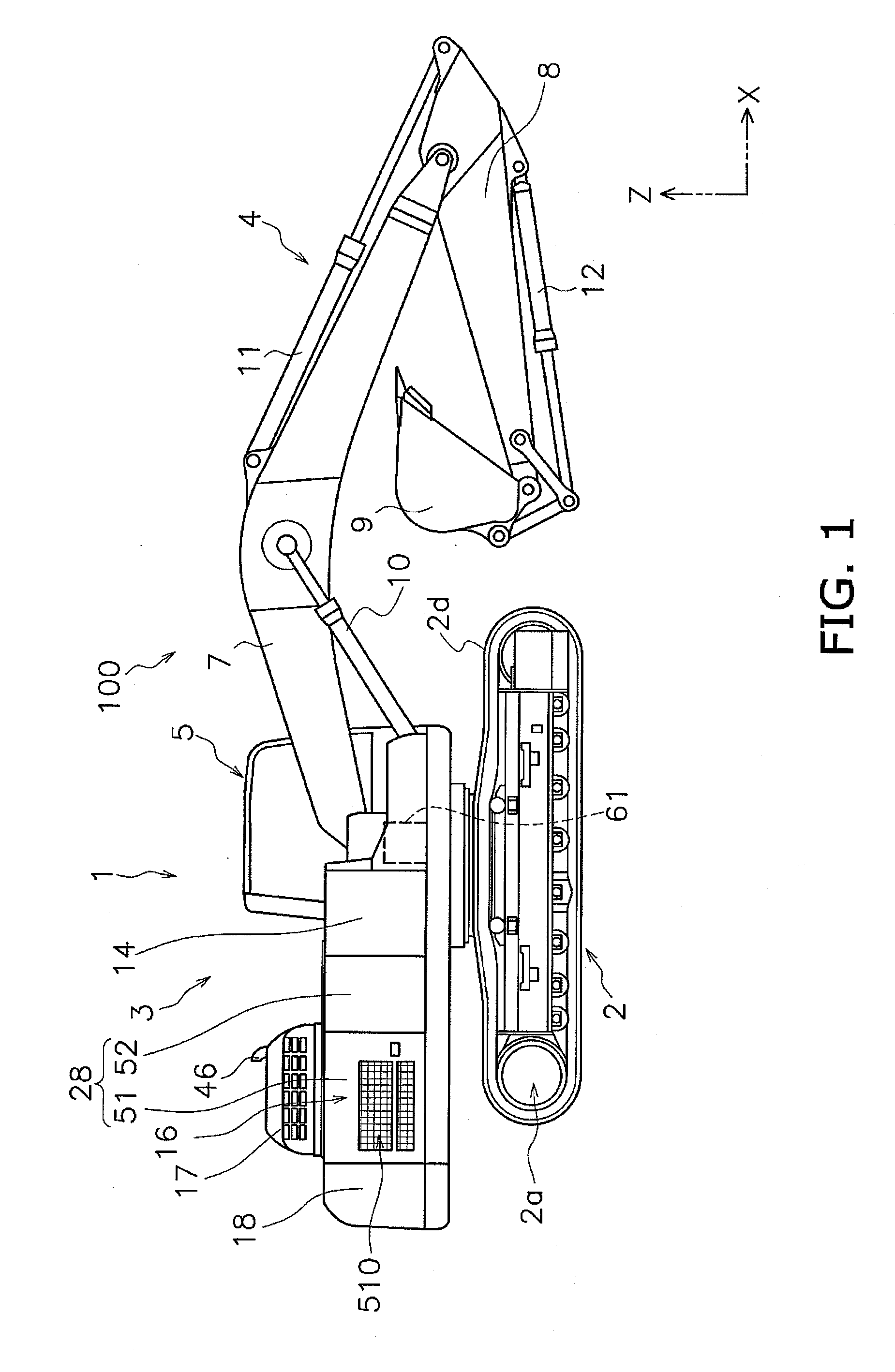
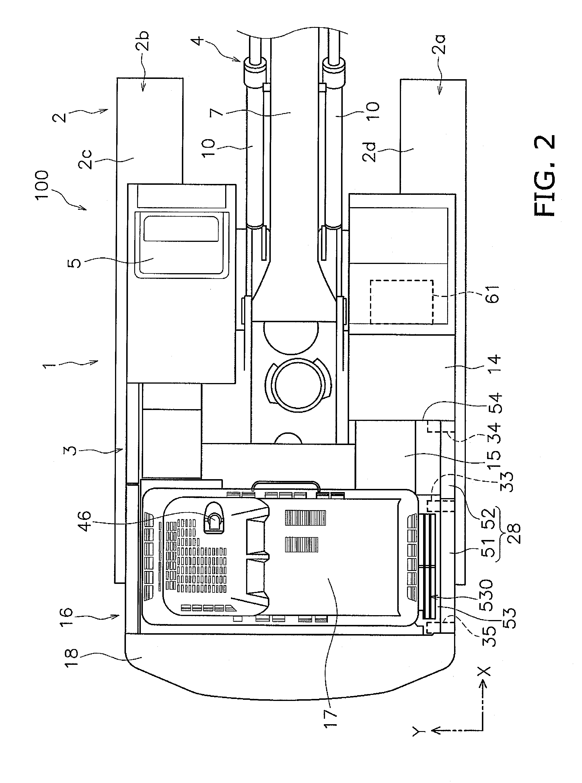
[0040]Below, a hydraulic excavator 100 according to an embodiment of the present invention will be described with reference to the diagrams. FIG. 1 is a side surface diagram of the hydraulic excavator 100. FIG. 2 is a planar diagram of the hydraulic excavator 100. As shown in FIG. 1 and FIG. 2, the hydraulic excavator 100 is provided with a vehicle body 1 and a work implement 4.

[0041]The vehicle body 1 has a moving body 2 and a revolving body 3. As shown in FIG. 2, the moving body 2 has a pair of moving apparatuses 2a and 2b. The moving apparatus 2a has a track 2d. The moving apparatus 2b has a track 2c. The moving apparatuses 2a and 2b move the hydraulic excavator 100 by driving the tracks 2c and 2d using driving force from an engine 21 (refer to FIG. 3) which will be described later.

[0042]Here, in the following description, the front and back direction has the meaning of the front and back direction of the vehicle body 1. In other words, the front and back direction is a direction...


PUM


Abstract

A hydraulic excavator includes an engine, a selective catalytic reduction apparatus, an outer cover, a first column member, a reducing agent tank, and a reducing agent pump. The selective catalytic reduction apparatus processes exhaust from the engine. The first column member supports the outer cover. The reducing agent tank retains a reducing agent. The reducing agent pump supplies the reducing agent from the reducing agent tank to the selective catalytic reduction apparatus. The reducing agent pump is attached to the first column member.

Description

CROSS-REFERENCE TO RELATED APPLICATIONS[0001]This application is a U.S. National stage application of International Application No. PCT / JP2013 / 053720, filed on Feb. 15, 2013.BACKGROUND[0002]1. Field of the Invention[0003]The present invention relates to a hydraulic excavator.[0004]2. Background Information[0005]An exhaust processing apparatus which processes exhaust from an engine is mounted onto a hydraulic excavator. The exhaust processing apparatus includes a selective catalytic reduction apparatus. The selective catalytic reduction apparatus reduces nitrogen oxide (NOx) in the exhaust.[0006]The selective catalytic reduction apparatus processes the exhaust using a reducing agent such as aqueous urea. As a result, a reducing agent tank and a reducing agent pump are mounted onto the hydraulic excavator. The reducing agent tank retains the reducing agent. The reducing agent pump supplies the reducing agent from the reducing agent tank to the selective catalytic reduction apparatus.[...

Claims


Application Information

Patent Timeline
IPC IPC(8): B60K13/04F01N3/24
CPCF01N3/24B60K13/04E02F9/0866E02F9/0883F01N3/2066F01N13/1805F01N2340/04F01N2590/08F01N2610/02B60Y2200/412Y02A50/20Y02T10/12
Inventor SAWADA, MASAHIRO
Owner KOMATSU LTD
Why Eureka
Try Eureka