Spraying head assembly for massaging tub

a tub and head technology, applied in boring tools, lighting and heating apparatus, combustion process, etc., can solve the problems of increasing assembly cost, reducing and reducing the cost of assembly, so as to prevent the motor from being worn out, enhance the massaging effect, and enhance the effect of massaging

Inactive Publication Date: 2006-01-31
2053961 ONTARIO
View PDF6 Cites 21 Cited by
  • Summary
  • Abstract
  • Description
  • Claims
  • Application Information

AI Technical Summary

Benefits of technology

[0007]Another objective of the present invention is to provide a spraying head assembly, wherein the water is pressurized by rotation of the helical blades of the vortex rotor and the helical plates of the water outlet valve seat to produce a strong water beam that is injected outward from the nozzle, thereby enhancing the massaging effect.
[0008]A further objective of the present invention is to provide a spraying head assembly, wherein the cover has a periphery formed with a plurality of water inlet holes, so that the spraying head assembly will not be blocked or choked by articles, thereby preventing the motor from being worn out due to an idling operation.
[0009]A further objective of the present invention is to provide a spraying head assembly, wherein the two water outlet openings of the impulse rotor can co-operate with the transverse bar of the nozzle, so that the water beam injected from the nozzle has an impulse oscillation effect, thereby greatly enhancing the massaging effect.
[0010]A further objective of the present invention is to provide a spraying head assembly, wherein each of the two water outlet openings of the impulse rotor has a chamfered face, so that the water pressure can push the impulse rotor to rotate successively.
[0011]A further objective of the present invention is to provide a spraying head assembly, wherein the spraying head assembly can be detached from the massaging tub easily and conveniently, thereby facilitating replacement and maintenance of the spraying head assembly.

Problems solved by technology

However, it is necessary to assemble the circulation pipe 6, the water outlet pipe 7 and the air guide pipe 8 in the tub body 1, thereby complicating the assembly process and increasing costs of assembly.
Further, the circulation head 2 is easily choked by an article, such as the towel or the like, so that the circulation head 2 forms a closed state, thereby wearing the motor due to the idling operation.

Method used


Image

  • Spraying head assembly for massaging tub
  • Spraying head assembly for massaging tub
  • Spraying head assembly for massaging tub

Examples


Embodiment Construction

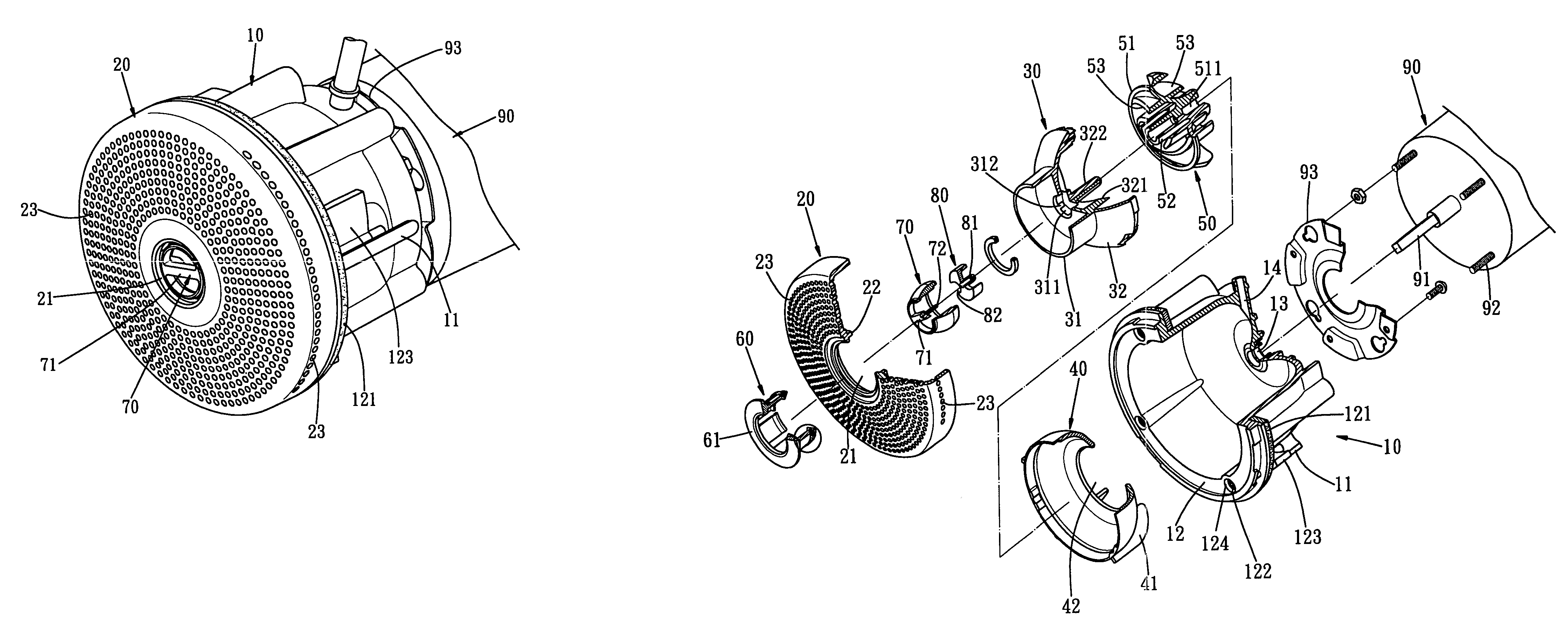
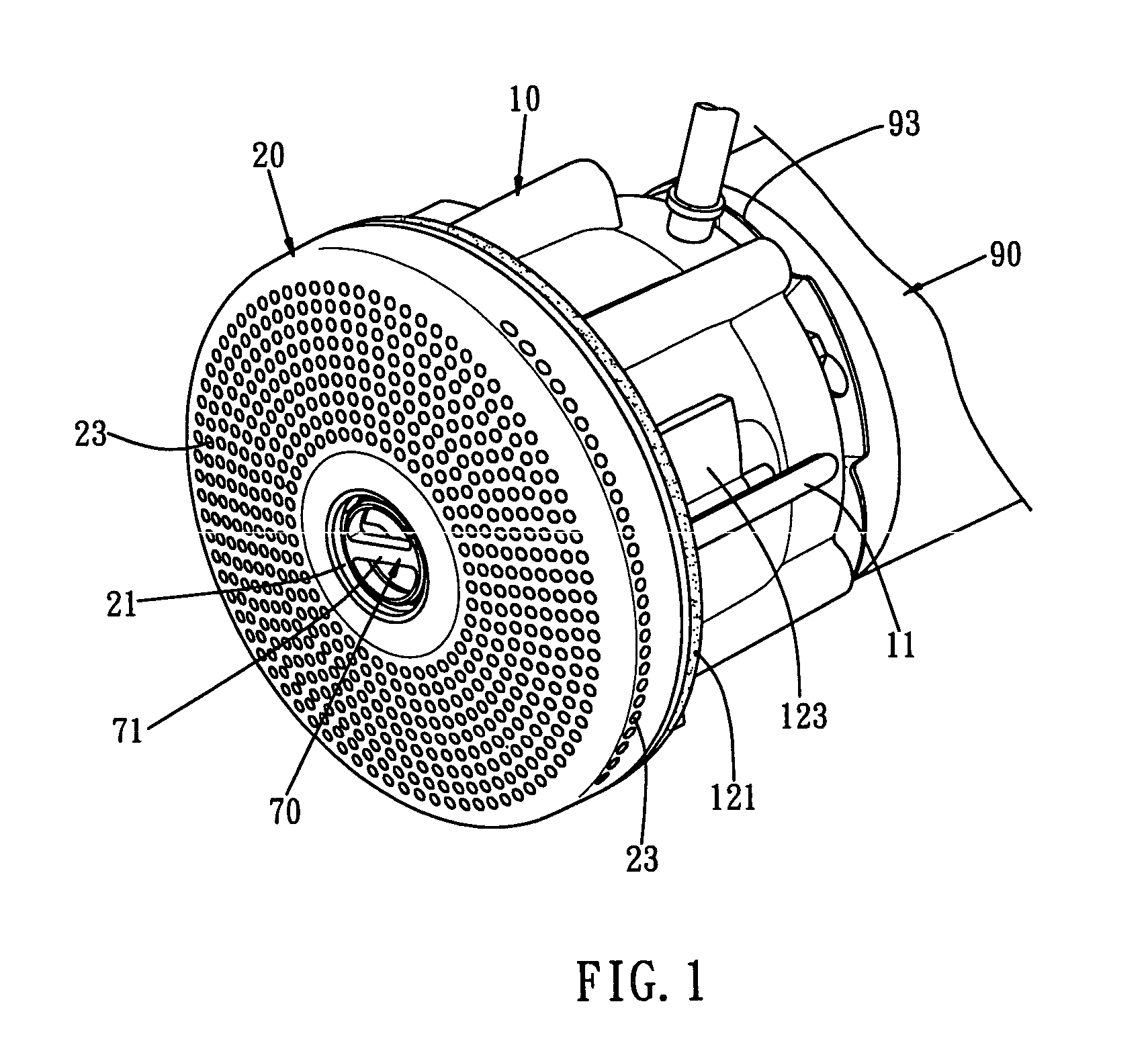
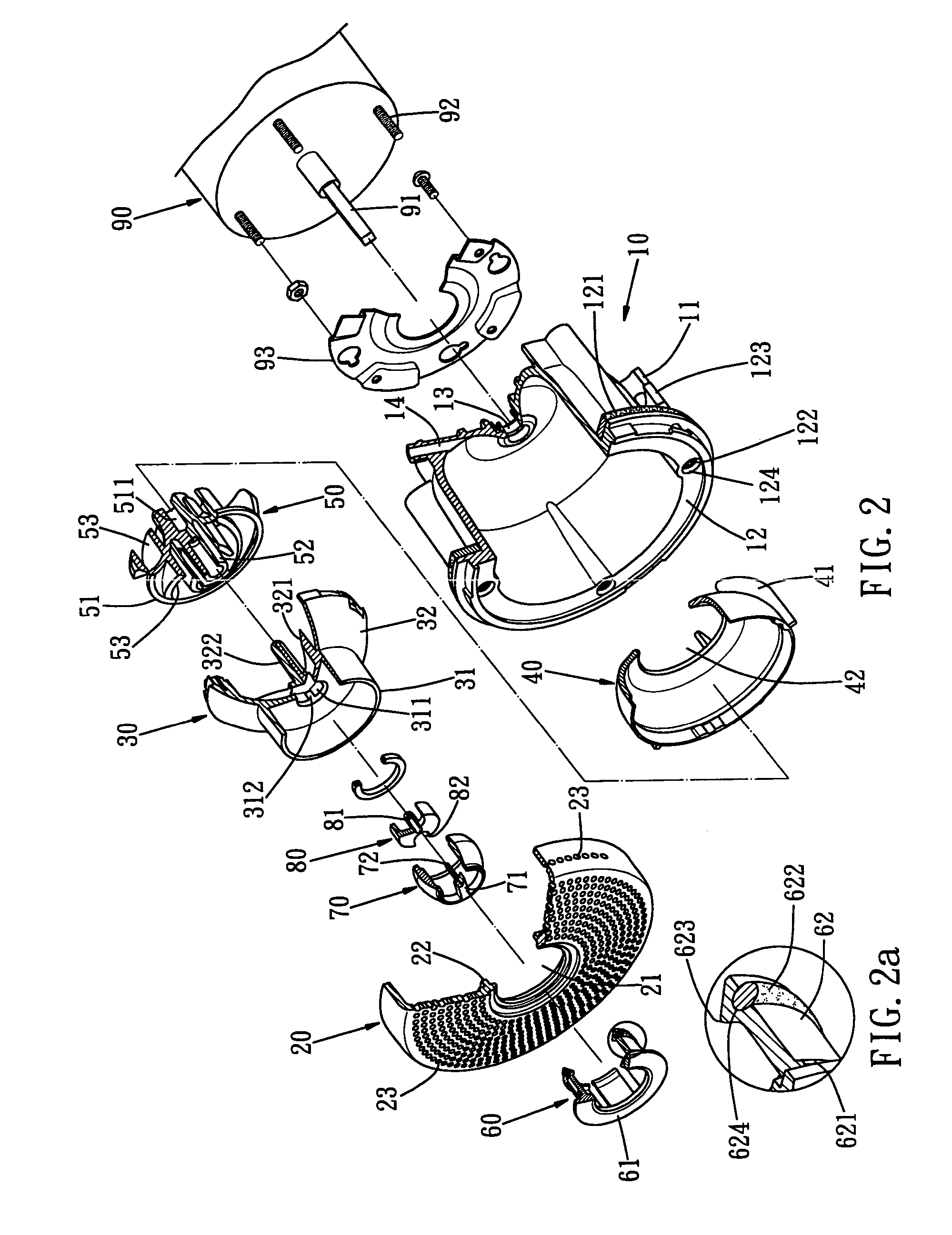
[0028]Referring to the drawings and initially to FIGS. 1–4, a spraying head assembly for a massaging tub in accordance with the preferred embodiment of the present invention comprises a housing 10, a cover 20, a water outlet valve seat 30, a water outlet valve cover 40, a vortex rotor 50, a bushing 60, a nozzle 70, an impulse rotor 80, and a motor 90.

[0029]The housing 10 is substantially cylindrical shaped, and has a periphery provided with a plurality of semi-circular posts 11. The housing 10 has an opened first end having a periphery formed with an annular lip 12. The housing 10 is provided with an O-ring 121 rested on a side of the lip 12. The housing 10 is provided with a plurality of locking screws 122 each extended through the lip 12, and a plurality of urging plates 123 each screwed on a respective one of the locking screws 122 and each connected to a respective one of the semi-circular posts 11. The lip 12 of the housing 10 is formed with a plurality of locking holes 124 for...


PUM


Abstract

A spraying head assembly for a massaging tub includes a housing, a cover, a water outlet valve seat, a water outlet valve cover, a vortex rotor, a bushing, a nozzle, an impulse rotor, and a motor. Thus, the water is pressurized by rotation of the helical blades of the vortex rotor and the helical plates of the water outlet valve seat to produce a strong water beam that is injected outward from the nozzle, thereby enhancing the massaging effect.

Description

BACKGROUND OF THE INVENTION[0001]1. Field of the Invention[0002]The present invention relates to a spraying head assembly, and more particularly to a spraying head assembly for a massaging tub.[0003]2. Description of the Related Art[0004]A conventional massaging tub in accordance with the prior art shown in FIG. 6 comprises tub body 1 having an inner wall provided with a circulation head 2, a drain head 3 and a plurality of nozzles 4, and a motor 5 mounted in the inside of the tub body 1. The motor 5 is connected to the circulation head 2 through a circulation pipe 6, and is connected to the nozzles 4 through a water outlet pipe 7. When the motor is started, the water contained in the tub body 1 is drawn through the circulation head 2, the circulation pipe 6 and the water outlet pipe 7, and is then injected outward from the nozzles 4, thereby providing a massaging effect. Each of the nozzles 4 is connected to an air guide pipe 8 which introduces the air into the nozzles 4 by the sip...

Claims


Application Information

Patent Timeline
Patent Type & Authority Patents(United States)
IPC IPC(8): B05B3/06A61H33/02B05B3/02
CPCA61H33/027B05B3/02A61H33/6063A61H33/6052A61H2201/1215
Inventor CHEN, JACK YA JYUE
Owner 2053961 ONTARIO
Why Eureka
Try Eureka