
In situ combustion turbine engine airfoil inspection

a combustion turbine engine and inspection technology, applied in the field of power generation, can solve the problems of labor-intensive procedures, time-consuming, and tbcs subject to degradation over their service li

Active Publication Date: 2006-01-31
SIEMENS ENERGY INC
View PDF20 Cites 81 Cited by
  • Summary
  • Abstract
  • Description
  • Claims
  • Application Information

AI Technical Summary

Benefits of technology

"The invention is a system and method for inspecting turbine blades in a combustion turbine engine. The system includes an image receptor, such as a camera, that is inserted into the inner turbine casing to provide a close-up view of the airfoil. The camera can be positioned using a positioner that is inserted radially into the inner turbine casing and can be rotated to image the airfoil from different angles. The system allows for improved resolution imaging of the airfoil and reduces the time and cost associated with traditional inspection methods. The technical effect of the invention is to provide a more efficient and effective way to inspect turbine blades in combustion turbine engines."

Problems solved by technology

However, TBCs are subject to degradation over their service life, and need to be inspected periodically to assess the integrity of the coating.
In-situ visual inspections may be performed without engine disassembly by using a borescope inserted into a combustion turbine engine, but such procedures are labor intensive, time consuming, and require that the combustion turbine engine be shut down, and the rotating parts held stationary for the inspection.

Method used


Image

  • In situ combustion turbine engine airfoil inspection
  • In situ combustion turbine engine airfoil inspection

Examples


Embodiment Construction

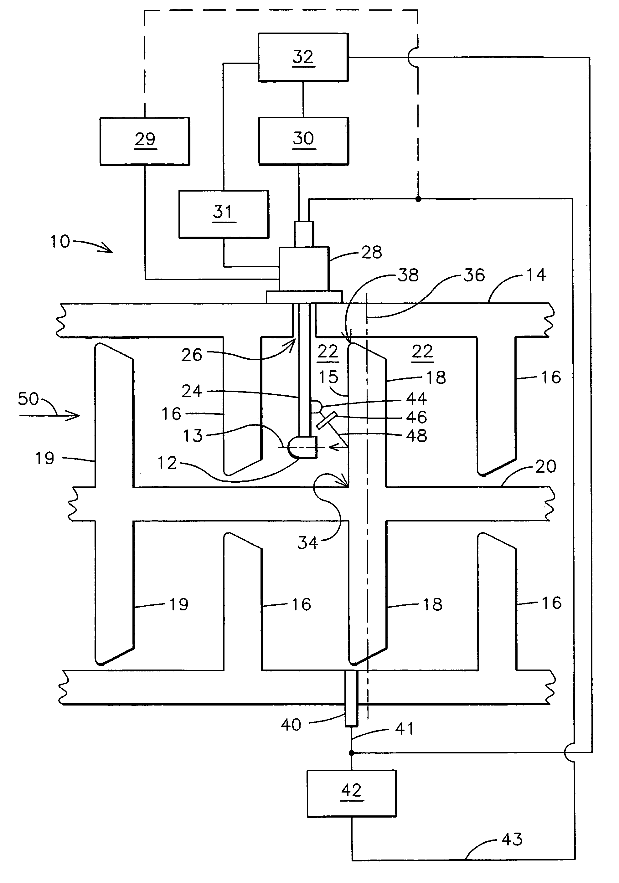
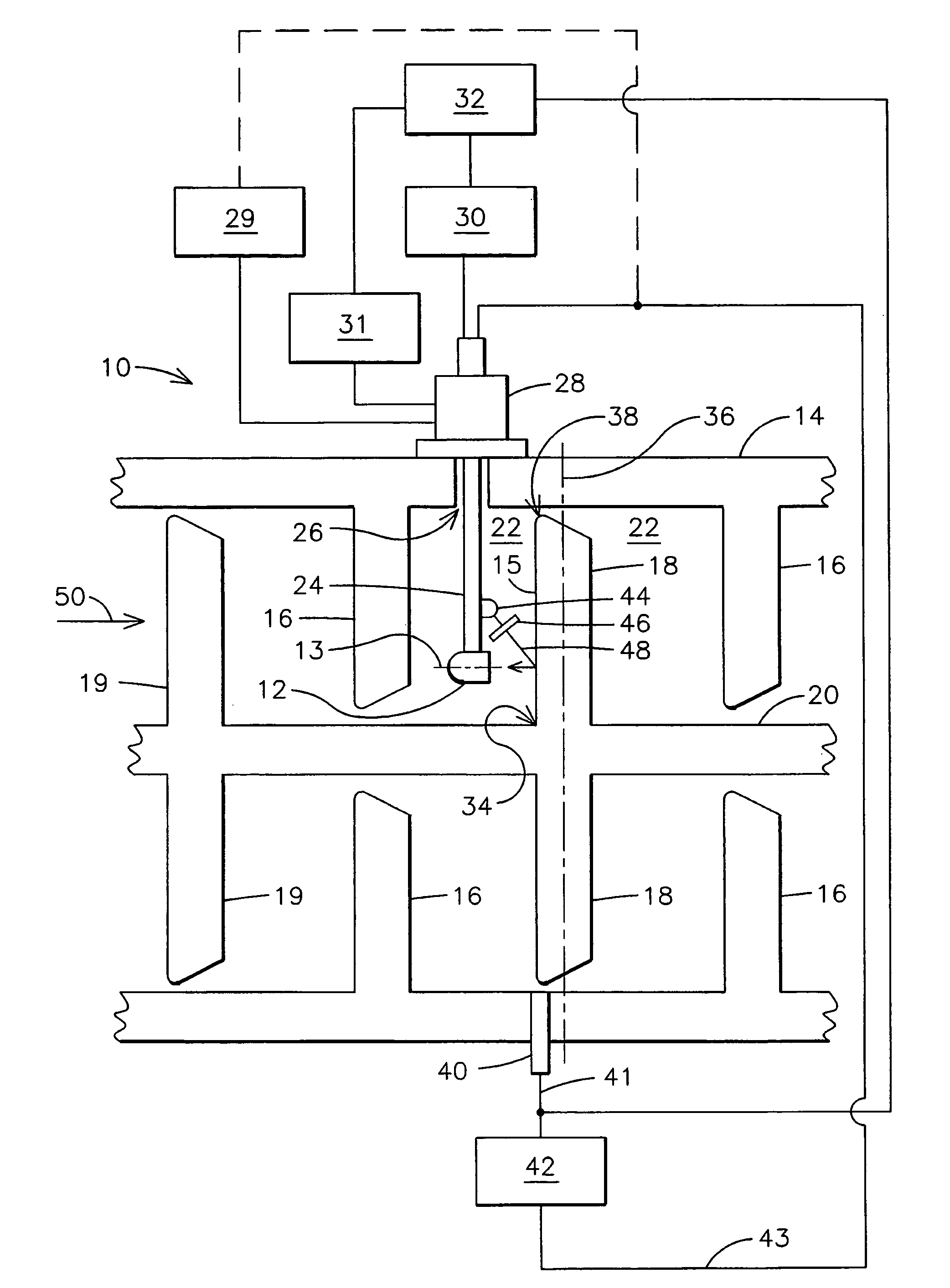
[0005]The inventor has developed an innovative imaging system and imaging method for in-situ inspection of combustion turbine engine airfoils, such as turbine blades and vanes. Advantageously, an image receptor may be inserted into an inner turbine casing to provide a relatively close-up view, such as perpendicular to an axis or surface of an airfoil, thereby providing a higher resolution image than is possible, for example, by imaging the airfoil from a position in a port of the inner turbine casing. The invention allows imaging of the airfoil for improved resolution along lines of view within 40 degrees of normal to the axis of the airfoil, and, for more improved resolution, within 20 degrees of normal to the axis of the airfoil. The image receptor may be capable of receiving energy, such as electromagnetic energy or acoustic energy, and be capable of conveying information about the airfoil outside of the inner turbine casing. For example, the image receptor may be a camera that c...


PUM

PropertyMeasurementUnit
angleaaaaaaaaaa
wavelengthaaaaaaaaaa

Abstract

A system (10) for imaging a combustion turbine engine airfoil includes a camera (12) and a positioner (24). The positioner may be controlled to dispose the camera within an inner turbine casing of the engine at a first position for acquiring a first image. The camera may then be moved to a second position for acquiring a second image. A storage device (30) stores the first and second images, and a processor (32) accesses the storage device to generate a composite image from the first and second images. For use when the airfoil is rotating, the system may also include a sensor (40) for generating a position signal (41) responsive to a detected angular position of an airfoil. The system may further include a trigger device (42), responsive to the position signal, for triggering the camera to acquire an image when the airfoil is proximate the camera.

Description

FIELD OF THE INVENTION[0001]This invention relates generally to the field of power generation, and more particularly, to inspection of turbine blades in a combustion turbine engine.BACKGROUND OF THE INVENTION[0002]Thermal barrier coatings (TBCs) applied to turbine airfoils are well known in the art for protecting parts such as blades and vanes from elevated operating temperatures within a combustion turbine engine. However, TBCs are subject to degradation over their service life, and need to be inspected periodically to assess the integrity of the coating. In the past, inspection of coated turbomachinery components has been performed by partially disassembling the combustion turbine engine and performing visual inspections on individual components. In-situ visual inspections may be performed without engine disassembly by using a borescope inserted into a combustion turbine engine, but such procedures are labor intensive, time consuming, and require that the combustion turbine engine...

Claims


Application Information

Patent Timeline
Patent Type & Authority Patents(United States)
IPC IPC(8): G01V8/00G01N21/86
CPCF01D5/005F01D21/003F05D2260/80
Inventor TWERDOCHLIB, MICHAEL
Owner SIEMENS ENERGY INC
Learn More