
Direction indicator system

Inactive Publication Date: 2006-01-31
BEVIN GARY FRASER
View PDF15 Cites 16 Cited by
  • Summary
  • Abstract
  • Description
  • Claims
  • Application Information

AI Technical Summary

Benefits of technology

[0006]It is an object of the invention to provide a direction indicator system that ameliorates some of

Problems solved by technology

Injuries and fatalities can occur particularly when the visibility of road cyclists is significantly compromised (between dusk and dawn and also on overcast days) and when cyclists change their direction of travel.
Whilst most of these devices illuminate the user, they do not necessarily indicate to other road users the direction or change of direction the user may take during the course of their travels.
Although these devices can be used to indicate a particular direction of travel, they require manual switching to activate and deactivate the devices which could cause a user to become distracted which could lead to injury or even fatality.

Method used


Image

  • Direction indicator system
  • Direction indicator system
  • Direction indicator system

Examples


Embodiment Construction

[0055]Referring now to the drawings, which show a preferred embodiment of the invention, namely a direction indicating system for use with a cyclist and cycle. This particular embodiment is for purely illustrative purposes only and is no way intended to be limiting as other embodiments (not illustrated) are envisaged.

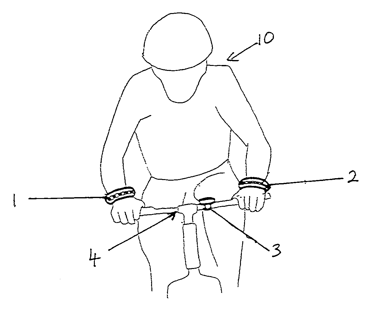
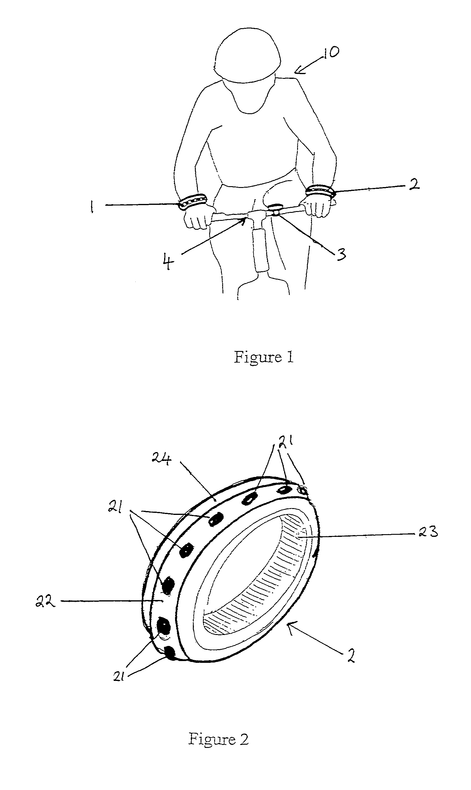
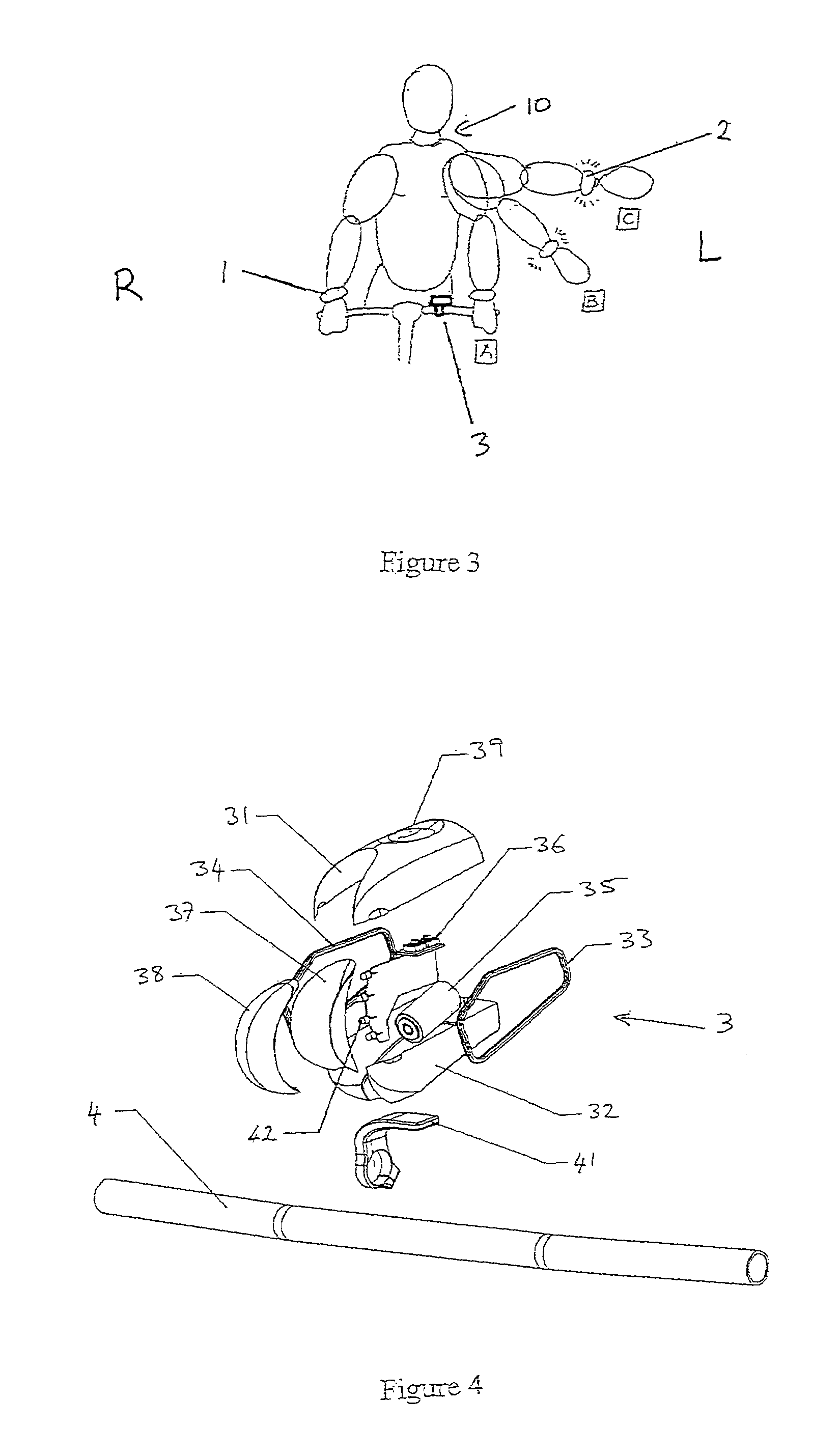
[0056]Turning to FIG. 1 there is shown the direction indicator system in use with a cyclist and cycle, preferably between dusk and dawn. However, it is envisaged that the direction indicator system could be used during daylight hours, especially when visibility is poor. The direction indicating system comprises a sensor 3 and direction indicating means 1 and 2. As shown in FIG. 1 the sensor 3 is mounted on the handle bars 4 of a cycle and the direction indicating means 1 and 2 (hereinafter “wrist devices”) are attached to the wrist of a cyclist 10. The wrist devices 1 and 2 as shown in FIG. 1 are in the deactivated mode due to the sensor 3 sensing that wrist devices 1 a...


PUM


Abstract

A direction indicator system and associated method for cyclists, joggers and other users includes one or more direction indicating elements and a cooperating sensor structured to sense the position of the direction indicating means such that when a direction indicating element is moved out of the sensing zones, the indicator is activated, and when the direction indicating element moves within the sensing zone, it is deactivated. In one embodiment, a pair of indicators is employed and may be used to indicate direction of intended movement of a cyclist.

Description

FIELD OF INVENTION[0001]This invention relates to a direction indicator system in particular, but not limited thereto, for cyclists.BACKGROUND OF INVENTION[0002]Despite the introduction of a number of products in the market place designed to improve the visibility and safety of cyclists, road safety organisations in New Zealand remain concerned about the nature and extent of injuries and fatalities in the cycling population. Injuries and fatalities can occur particularly when the visibility of road cyclists is significantly compromised (between dusk and dawn and also on overcast days) and when cyclists change their direction of travel.[0003]There are known lighting devices either mounted on the cycle or worn by a user that enhance the visibility of the cyclist to other road users. Whilst most of these devices illuminate the user, they do not necessarily indicate to other road users the direction or change of direction the user may take during the course of their travels.[0004]It is ...

Claims


Application Information

Patent Timeline
IPC IPC(8): B62J6/00
CPCB62J6/005B60Q1/36B62J6/055
Inventor LOVEGROVE, DAVID
Owner BEVIN GARY FRASER
Learn More