Hiding geo-location data through arrangement of objects

a geo-location and object technology, applied in the field of steganography and data hiding, can solve the problem of artwork that requires little, if any, further modification

Inactive Publication Date: 2006-01-31
DIGIMARC CORP (FORMERLY DMRC CORP) +1
View PDF134 Cites 168 Cited by
  • Summary
  • Abstract
  • Description
  • Claims
  • Application Information

AI Technical Summary

Benefits of technology

[0011]To further aid the security document designer, data defining several different information-carrying patterns (both watermark and/or calibration pattern) can be stored on mass storage of a computer a workstation and serve as a library of design elements for future designs. The same user-interface techniques that are employed to pick colors in image-editing software (e.g. Adobe Photoshop) and fill textures in presentation programs (e.g. Microsoft PowerPoint) can similarly be used to present a palette of information patterns to a security document designer. Clicking on a visual representation of the desired pattern makes the pattern available for inclusion in a security document being designed (e.g. filling a desired area).
[0

Problems solved by technology

Even loose compliance can result in artwork that requires little, if any, fur

Method used


Image

  • Hiding geo-location data through arrangement of objects
  • Hiding geo-location data through arrangement of objects
  • Hiding geo-location data through arrangement of objects

Examples


Embodiment Construction

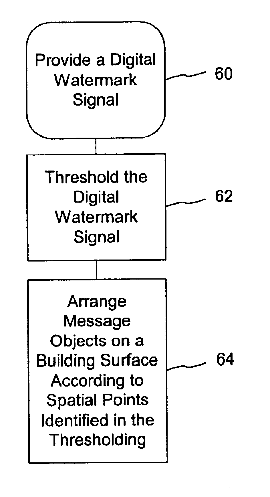
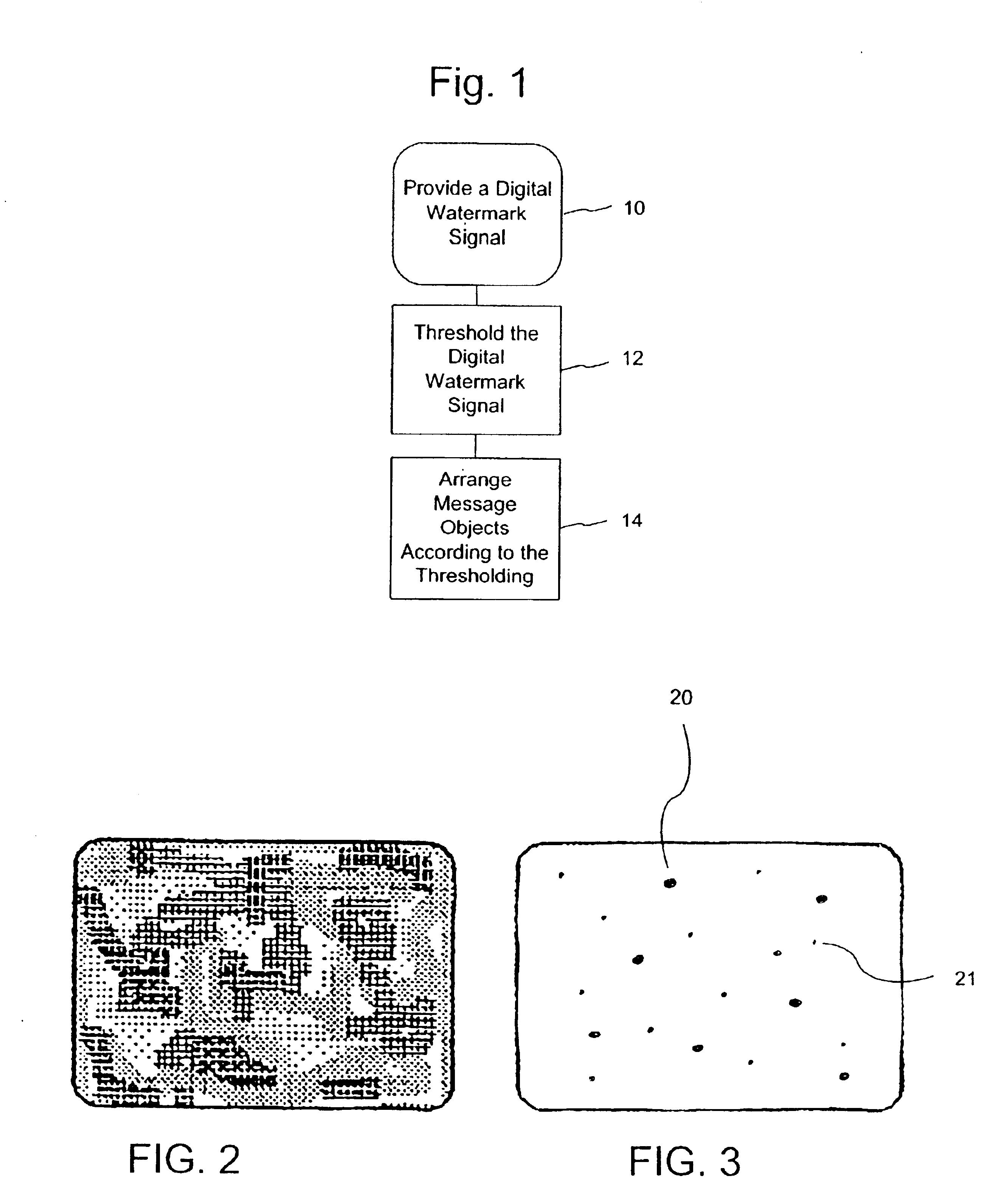
[0022]We have found that the arrangement of objects within an image can be used to convey information—which is otherwise imperceptible to a human viewer. We arrange so-called “message objects” to convey or represent a steganographic signal (e.g., a digital watermark). We define a message object broadly herein as including an information carrier, an image object, a shape, an object or collection of objects, a pixel or group of pixels, a physical object, paint or other covering, surface texture, a contrast or color / gray-scale area, etc. A set of message objects is arranged within an image or area to form a steganographic message. A few examples are provided below.

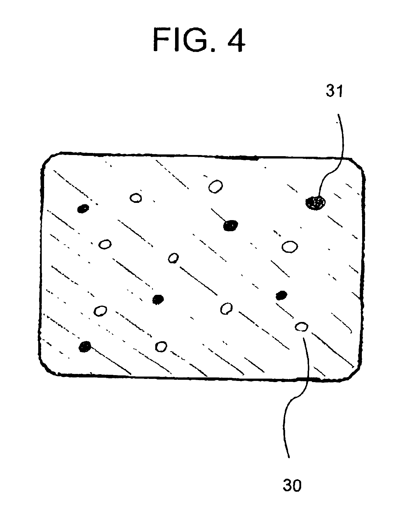
[0023]Consider a drawing illustrating a Dalmatian puppy. The puppy has a white coat complimented with black spots. An artist (or digital editor) can arrange a set of spots—an example of our message objects—so as to convey a hidden or steganographic message. More practical, however, is to align the spots according to a predete...


PUM

PropertyMeasurementUnit
Structureaaaaaaaaaa
Surfaceaaaaaaaaaa
Distanceaaaaaaaaaa

Abstract

The present invention provides steganographic-embedding techniques. In one implementation a digital watermark signal is mapped to a set of spatial positions. Physical message objects are positioned according to the set of spatial positions. The signal is provided on a physical structure such as a building or road. The signal may include geo-location information. The geo-location information identifies the location of the physical structure. In other cases the signal includes a marker or identifier. The marker or identifier provides a reference point for images depicting the physical structure.

Description

RELATED APPLICATION DATA[0001]The present application is a continuation in part of U.S. patent application Ser. No. 10 / 074,680, filed Feb. 11, 2002. The present application is also a continuation in part of U.S. patent application Ser. No. 09 / 939,298, filed Aug. 24, 2001 (now U.S. Pat. No. 6,804,379), which is a continuation in part of U.S. patent application Ser. No. 09 / 127,502, filed Jul. 31, 1998 (now U.S. Pat. No. 6,345,104), which is a continuation-in-part of U.S. patent application Ser. No. 09 / 074,034, filed May 6, 1998 (now U.S. Pat. No. 6,449,377). The Ser. No. 09 / 127,502 application is also a continuation-in-part of U.S. patent application Ser. No. 08 / 967,693, filed Nov. 12, 1997 (now U.S. Pat. No. 6,122,392), which is a continuation of application Ser. No. 08 / 614,521, filed Mar. 15, 1996 (now U.S. Pat. No. 5,745,604), which is a continuation of application Ser. No. 08 / 215,289, filed Mar. 17, 1994 (now abandoned). The Ser. No. 09 / 127,502 application is also a continuation-i...

Claims


Application Information

Patent Timeline
IPC IPC(8): H04K1/00B29C45/14B42D15/00G06T1/00G06V30/40G07C9/00G07D7/00G07D7/12G07F7/08G07F7/10G07F7/12G07F17/16G10L19/00G11B20/00H04B1/66H04N1/00H04N1/32H04N5/913
CPCB42D25/29G06Q20/341G06Q20/40145G06T1/0021G07C9/00079G07D7/0013G07D7/002G07D7/004G07F7/08G07F7/086G07F7/1008G07F7/1016G07F7/12G10L19/018H04B1/665H04N1/00005H04N1/00037H04N1/00079H04N1/32144H04N1/32208H04N1/32219H04N1/32251H04N1/32261H04N1/32288H04N1/32304H04N1/32352H04N5/913H04N21/23892H04N21/8358G06K9/00442B29C45/1418G06T2201/0052G11B20/00086G11B20/00094G11B20/00115G11B20/00166G11B20/00181G11B20/00884G11B20/00891H04N1/32122H04N2005/91321H04N2005/91335H04N2201/3205H04N2201/3207H04N2201/3225H04N2201/3226H04N2201/3233H04N2201/3239H04N2201/327H04N2201/3271H04N2201/3274H04N2201/328G07D7/0032G07D7/0034G07C9/253G06V30/40
Inventor PATTERSON, PHILIP R.LOFGREN, NEIL E.STACH, JOHNRHOADS, GEOFFREY B.
Owner DIGIMARC CORP (FORMERLY DMRC CORP)
Why Eureka
Try Eureka