
Listing activities in a graphical user interface in a collaborative work tool Architecture

a collaborative work and activity technology, applied in the field of meeting facilitating software, can solve the problems of not being able to integrate with the basic functionality provided, and the software based scheduling system providing little additional functionality above and beyond

Inactive Publication Date: 2006-01-31
ACCENTURE GLOBAL SERVICES LTD
View PDF20 Cites 75 Cited by
  • Summary
  • Abstract
  • Description
  • Claims
  • Application Information

AI Technical Summary

Benefits of technology

The patent describes a system, method, and program for creating a graphical user interface for a collaborative work tool. The interface allows users to define activities and view their status. The system automatically collects background information about the activity and sends it to users in real-time. The system also allows users to send the activity to a database or a specific participant user. The technical effect of this invention is to provide a more efficient and effective way for users to collaborate and share their work with each other.

Problems solved by technology

It is a problem in the field of scheduling systems to provide a calendar based system which is both simple to use and provides adequate functionality to justify a company or user in investing in and making use of such a system.
These enhancements are disjunct in that they do not integrate with the basic functionality provided by the calendar system.
Thus, the software based scheduling systems provide little additional functionality above and beyond those provided by the paper based systems and do not in and of themselves represent a breakthrough in the field of scheduling systems.

Method used


Image

  • Listing activities in a graphical user interface in a collaborative work tool Architecture
  • Listing activities in a graphical user interface in a collaborative work tool Architecture
  • Listing activities in a graphical user interface in a collaborative work tool Architecture

Examples


Embodiment Construction

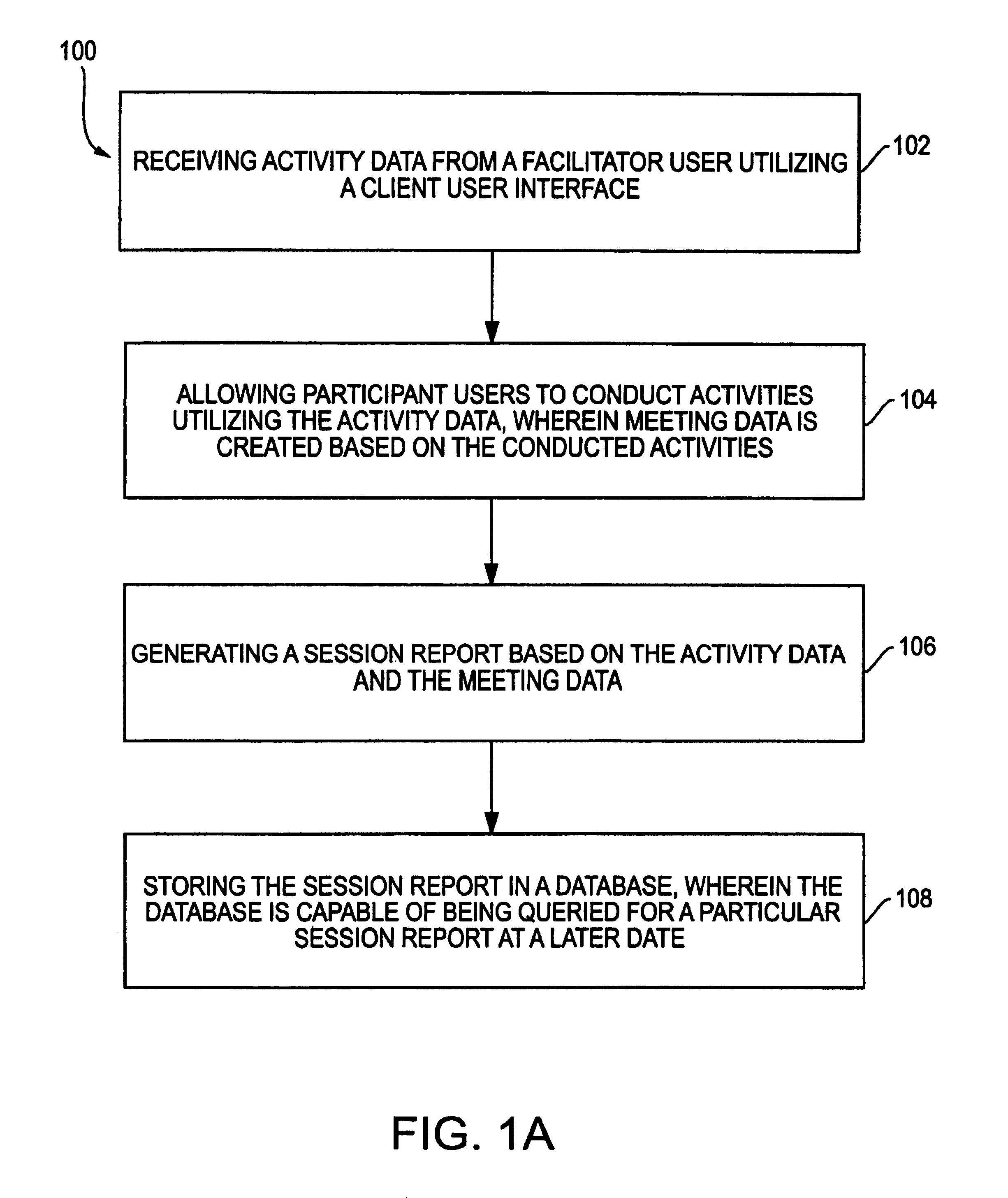
[0040]FIG. 1A is a flowchart illustrating a method 100 for affording a collaborative work tool environment, in accordance with an embodiment of the present invention. First, in operation 102, activity data is received from a facilitator user utilizing a client user interface. Then, in operation 104, participant users are allowed to conduct activities utilizing the activity data, wherein meeting data is created based on the conducted activities. A session report is then generated based on the activity data and the meeting data, as indicated in operation 106. Finally, in operation 108, the session data is stored in a database, wherein the database is capable of being queried for a particular session at a later date.

[0041]The present invention is a platform-independent tool that supports both asynchronous and synchronous sessions, independent of the physical whereabouts of the participants. The present invention offers a range of activities, —such as brainstorming and discussion. Advan...


PUM


Abstract

A system, method and program are provided for listing activities in a graphical user interface in a collaborative work tool framework. An activity window having activity description data, activity start data, activity duration data, and an activity status data is displayed. Then, an activity is defined in response to user selection of a defined activity button and the defined activity is displayed in the activity window. Next, status for the defined activity is determined based on the start time and the duration for the defined activity. Finally, background information relevant to the defined activity is automatically acquired, including automatically obtaining the activity description when the start time is within a predetermined period, parsing and pattern matching the activity description to identify searchable components thereof, querying a plurality of sources across a network to obtain the background information, and receiving the background information in response to querying the plurality of sources.

Description

FIELD OF THE INVENTION[0001]The present invention relates to meeting facilitating software and more particularly to electronic, collaborative work tools.BACKGROUND OF THE INVENTION[0002]It is a problem in the field of scheduling systems to provide a calendar based system which is both simple to use and provides adequate functionality to justify a company or user in investing in and making use of such a system. There are numerous calendar based time planning systems presently available, and many of these are paper based wherein the user is provided with a calendar which is segmented by a particular time period desired by the user. There are daily, weekly, monthly calendar systems and systems which incorporate combinations of these time periods to enable an individual to schedule meetings and to plan out their daily activities. What differentiates the various scheduling systems embodied in these calendars is the additional features provided by the format used to present the calendar i...

Claims


Application Information

Patent Timeline
Patent Type & Authority Patents(United States)
IPC IPC(8): G09G5/00
CPCG06Q10/0631G06Q10/10Y10S715/963
Inventor DANIELSEN, BJORN I.MEROK, PETTERFEVANG, PAL K.
Owner ACCENTURE GLOBAL SERVICES LTD
Learn More