Contaminant deposition control baffle for a capacitive pressure transducer

a capacitive pressure transducer and control baffle technology, applied in fluid pressure measurement, variable capacitors, instruments, etc., can solve the problems of large volume of particles or contaminants, output signals generated by such transducers, and undesirable characteristics of varying response, so as to prevent, reduce as much, the effect of contaminants on the performance of the transducer

Inactive Publication Date: 2006-02-07
MKS INSTR INC
View PDF163 Cites 48 Cited by
  • Summary
  • Abstract
  • Description
  • Claims
  • Application Information

AI Technical Summary

Benefits of technology

[0018]Prior art filtration techniques attempted to prevent, or reduce as much as possible, contaminants from reaching the diaphragm of capacitive pressure transducers. The present invention provides an alternate approach. Instead of eliminating contaminants, a baffle constructed according to the invention steers contaminants to the diaphragm in an predetermined pattern so as to minimize the effect that such contaminants can have on performance of the transducer.

Problems solved by technology

Some of the processes used in integrated circuit fabrication, such as the etching of aluminum, tend to generate a large volume of particles or contaminants.
However, the output signals generated by such transducers have the undesirable characteristic of varying in response to “planar shifts” of the diaphragm.
When such contaminants become deposited on diaphragm 160, they can adversely affect the accuracy of transducer 100.

Method used


Image

  • Contaminant deposition control baffle for a capacitive pressure transducer
  • Contaminant deposition control baffle for a capacitive pressure transducer
  • Contaminant deposition control baffle for a capacitive pressure transducer

Examples


Embodiment Construction

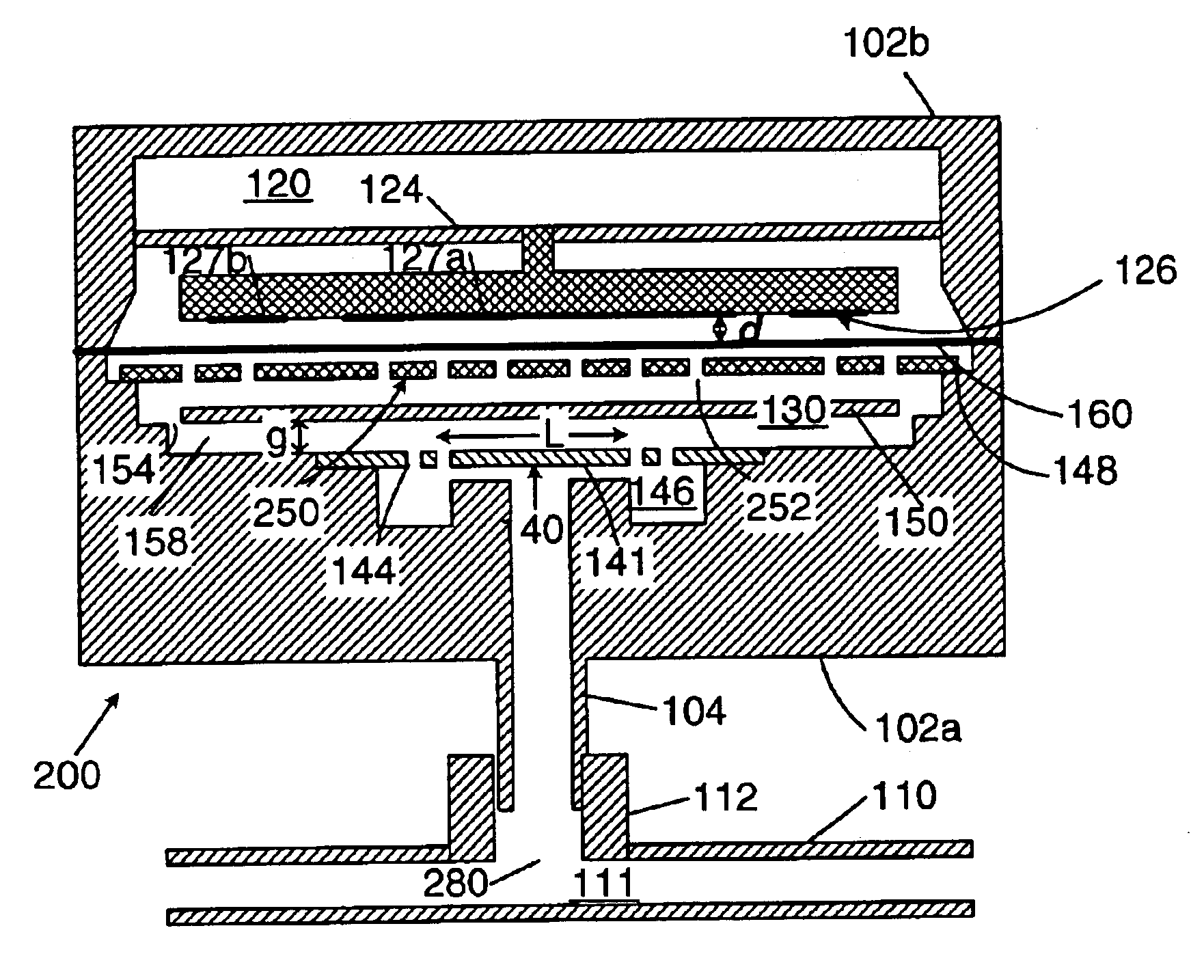
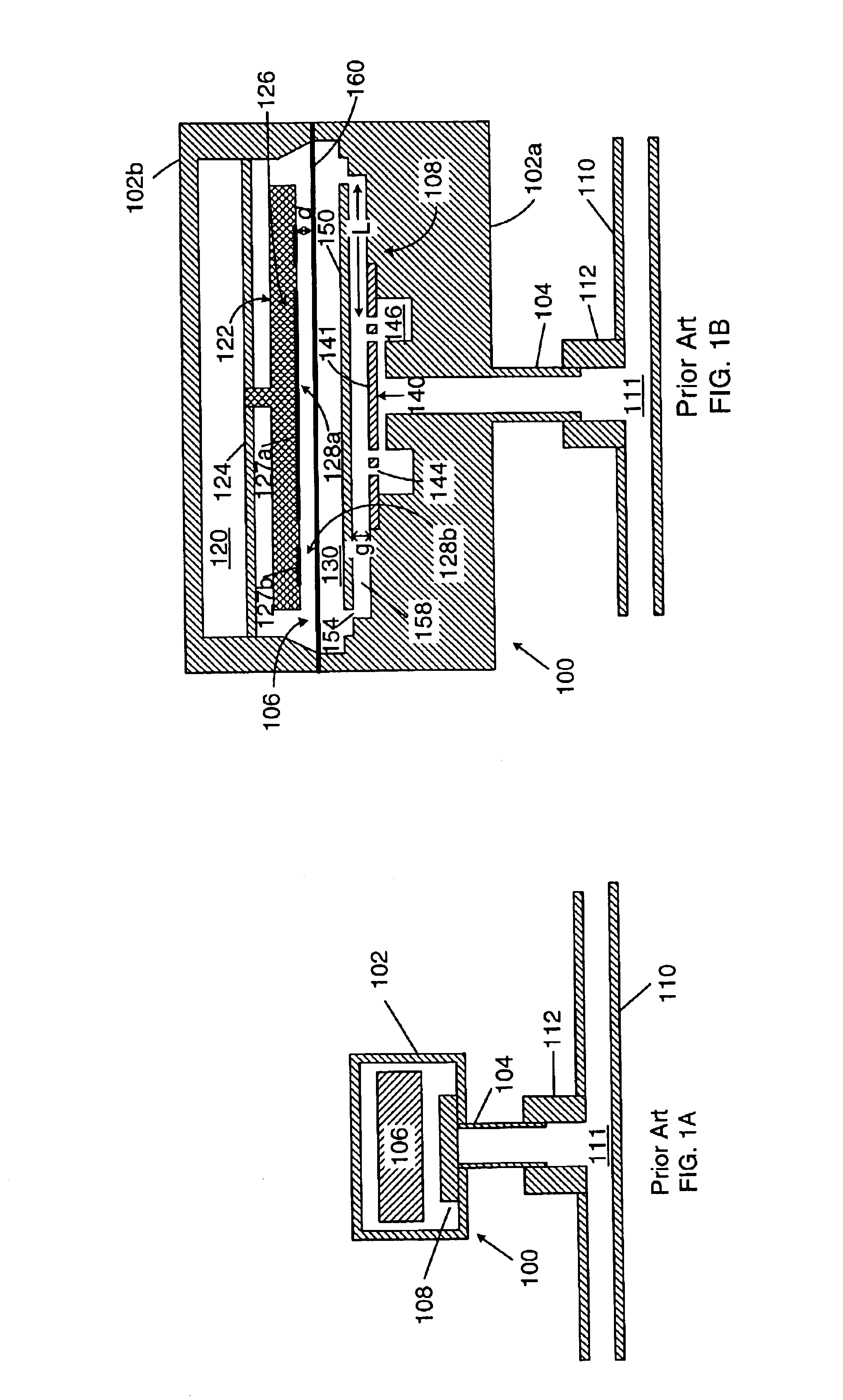
[0031]FIG. 4A shows a sectional side view of a capacitive pressure transducer 200 constructed according to the present invention. In addition to the components shown (in FIG. 1B) in prior art pressure transducer 100, transducer 200 also contains a deposition controlling baffle 250 disposed in internal chamber 130 between diaphragm 160 and baffle 150. Material (e.g., gas molecules or particle contaminants) entering pressure transducer 200 enters through gas line 110 and passes through trap system 140, baffle 150, and finally through deposition controlling baffle 250 before contacting diaphragm 160. As will be further explained below, baffle 250 redirects the flow of contaminants within chamber 130 so as to control zero shifts within pressure transducer 200.

[0032]FIG. 4B shows an expanded view of a portion of transducer 200. More specifically,

[0033]FIG. 4B shows an expanded sectional side view of electrode 122 and diaphragm 160. As shown, diaphragm 160 may be thought of as being segme...


PUM

PropertyMeasurementUnit
aspect ratioaaaaaaaaaa
lengthaaaaaaaaaa
lengthaaaaaaaaaa

Abstract

The disclosed transducer includes a housing, a diaphragm, an inner conductor, an outer conductor, and a first baffle. The housing defines an interior volume. The diaphragm is disposed in the housing and divides the interior volume into a first chamber and a second chamber. The diaphragm flexes in response to pressure differentials in the first and second chambers. The inner conductor is disposed in the first chamber. The outer conductor is disposed in the first chamber around the inner conductor. The first baffle is disposed in the second chamber and defines an inner region, a middle region, and an outer region. The inner region underlies the inner conductor. The middle region underlies the outer conductor. The outer region underlies neither the inner conductor nor the outer conductor. The first baffle defines apertures in at least two of the inner, middle, and outer regions.

Description

BACKGROUND OF THE INVENTION[0001]The present invention is related to capacitive pressure transducers. More particularly, the present invention relates to controlling deposition of contaminants in capacitive pressure transducers.[0002]FIG. 1A shows a sectional side view of a prior art capacitive pressure transducer 100. For convenience of illustration, FIG. 1A, as well as other figures in the present disclosure, are not drawn to scale. As shown, transducer 100 includes a housing 102, a capacitive pressure sensor 106 disposed within housing 102, an inlet tube 104, and a filtering mechanism 108. For convenience of illustration, many details of transducer 100 are omitted from FIG. 1A. However, such sensors are well known and are described, for example, in U.S. Pat. Nos. 5,911,162 and 6,105,436 and U.S. patent application Ser. Nos. 09 / 394,804 and 09 / 637,980.[0003]Briefly, transducer 100 is normally coupled to a gas line 110, or some other external source of gas or fluid 11 by a coupling ...

Claims


Application Information

Patent Timeline
Patent Type & Authority Patents(United States)
IPC IPC(8): G01L9/12G01L9/00G01L19/06
CPCG01L19/0636G01L9/0075C23C16/00G01L9/12G01L19/06H01L21/00
Inventor LISCHER, D. JEFFREYTRAVERSO, ROBERT
Owner MKS INSTR INC
Why Eureka
Try Eureka