Vented plastic bottle

a plastic bottle and spout technology, applied in the field of containers, can solve the problems of glugging action, no longer leveling of the die top of the spout, and bottle customers' problems, and achieve the effect of removing glugging action

Active Publication Date: 2006-02-07
RING CONTAINER TECH LLC
View PDF7 Cites 16 Cited by
  • Summary
  • Abstract
  • Description
  • Claims
  • Application Information

AI Technical Summary

Benefits of technology

[0005]The primary object of the invention is to provide a container or bottle having a novel neck arrangement including anti-glugging structure which eliminates glugging action as liquid is poured from the container and reinforcing means for maintaining the neck arrangement in a substantially level position during the manufacture and use of the container.
[0006]Still another object of this invention resides in the above container wherein the anti-glug structure includes a generally horizontal curved ledge which deflects liquid toward the front edge of the outlet spout of the bottle as the liquid is poured from the bottle, and vertical columns or ribs extending downwardly from die ledge to the top of the bottle to strengthen the neck and maintain the spout in a level position during the manufacturing and filling operations of the bottle.

Problems solved by technology

However, an occasional problem has been noted.
During the cooling process of the hot, blown plastic bottle, the neck of the bottle may sometimes assume an excessively tilted position so that die top of the spout is no longer level.
This causes capping and sealing problems for the bottle customer during the filling operation.
The tilt problems have become more common as the thickness of the plastic material has been reduced for cost purposes and are deemed attributable to the fact that the no-glug ledge is unsupported in a vertical direction due to the open vertical space between the bottom of the ledge and the top wall of the container.

Method used


Image

  • Vented plastic bottle
  • Vented plastic bottle
  • Vented plastic bottle

Examples


Embodiment Construction

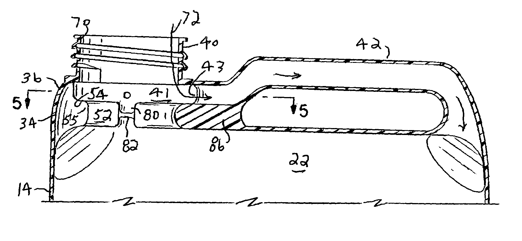
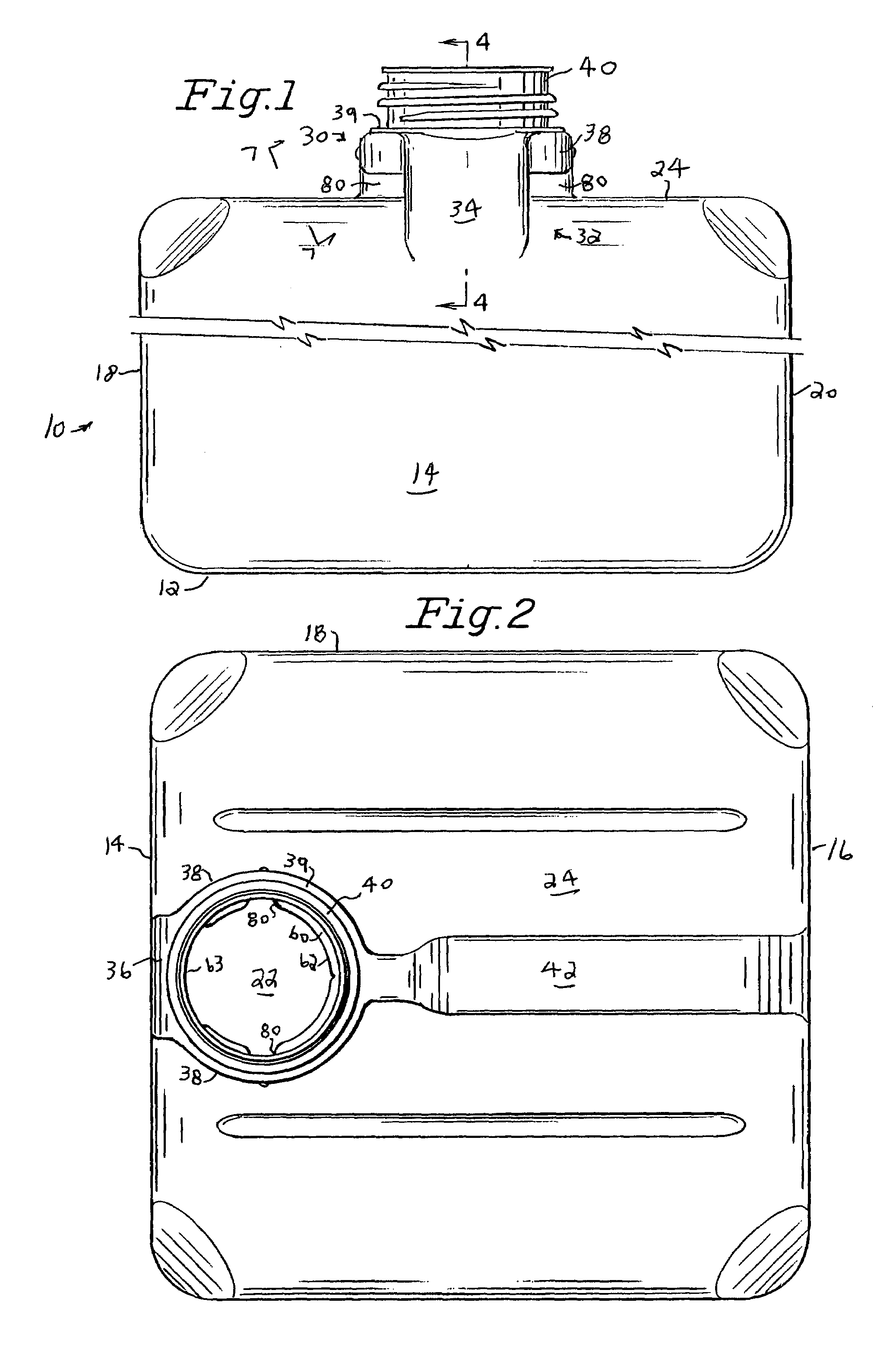
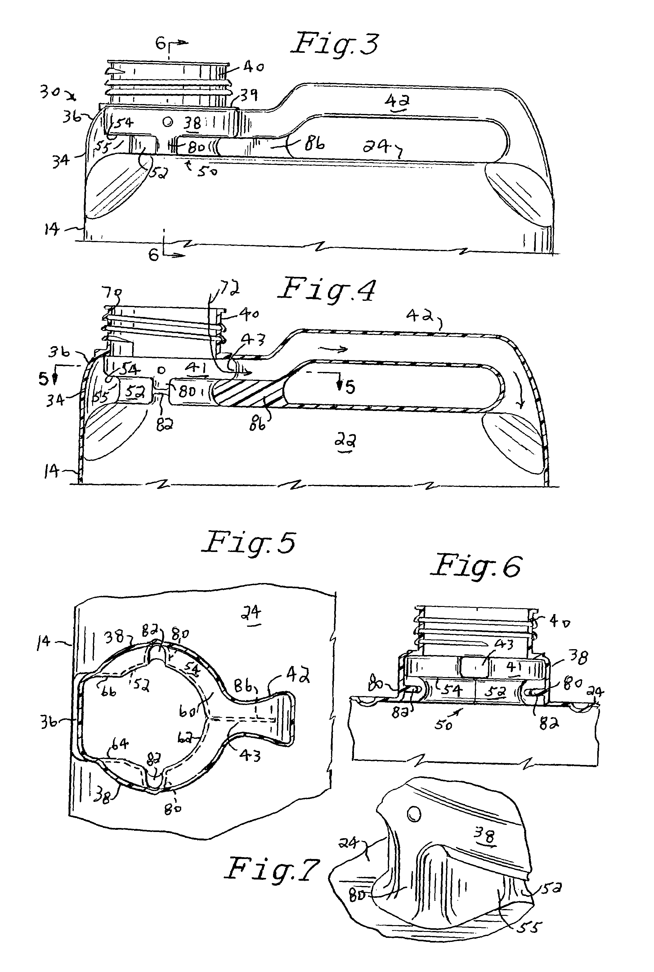
[0016]Referring now to the drawings the one piece blow molded plastic container or bottle 10 includes bottom wall 12, vertical front wall 14, rear wall 16 and side walls 18 and 20 which define a liquid containing chamber 22 of generally rectangular cross section and a top wall 24 joining walls 14, 16, 18 and 20 to close chamber 22.

[0017]Integrally formed on top of wall 24, adjacent front wall 14, is a neck platform 30 having a forward wall 32 including a vertical section 34 which extends along mid coextensively upwardly from front wall 14 and blends with a rearwardly curved section 36 that blends with a front portion of a circular side wall 38 and a flat top wall 39 on top of which is formed a circular threaded outlet spout 40 normally closed by a cap (not shown). Circular side wall 38 defines a transitional chamber 41 which extends rearwardly from wall 36 to an area where it connects to the forward end of a hollow passageway 43 of a narrow hollow handle 42 which is connected at its...


PUM


Abstract

A blow molded plastic container having a circular spout and a liquid guiding neck portion with a curved, generally U-shaped pouring anti-glug ledge. A plurality of vertical reinforcing columns extend between the ledge and top wall of the container to hold the spout in a level position.

Description

BACKGROUND OF THE INVENTION[0001]This invention relates generally to containers for dispensing liquid and more specifically to a container having a novel pouring spout arrangement by which the space above the liquid is vent ed to permit air to be drawn into the space during a pouring operation to prevent the glugging or gulping phenomenon associated with many conventional bottles.[0002]This invention is particularly applicable to larger blow molded plastic bottles, for example 35 lb. or 5 gallon jugs, of the type described in U.S. Pat. No. 5,340,000, owned by the parent company of the assignee of this invention, and used for dispensing a variety of different types of liquids, some of which may be toxic or flammable. To eliminate the unwanted glugging action, as liquid is poured from the bottle, the bottle illustrated in U.S. Pat. No. 5,340,000 includes a neck platform 30 having a forward wall 32 including a vertical section 34 which extends along and coextensively upwardly from wall...

Claims


Application Information

Patent Timeline
Patent Type & Authority Patents(United States)
IPC IPC(8): B65D83/00B65D25/28B65D25/40
CPCB65D25/2894B65D25/40B65D2525/282
Inventor DYGERT, DOUGLASSTALEY, PATRICKKUHAR, EUGENE
Owner RING CONTAINER TECH LLC
Why Eureka
Try Eureka