
Cartridge and printing apparatus

a printing apparatus and cartridge technology, applied in the field of cartridges, can solve the problems of insufficient reliability of prior art cartridges, inability to sufficiently ensure the reliability of detection, and inability to carry out detection under fixed detection conditions, so as to improve the reliability of information transmission.

Inactive Publication Date: 2006-02-07
SEIKO EPSON CORP
View PDF40 Cites 27 Cited by
  • Summary
  • Abstract
  • Description
  • Claims
  • Application Information

AI Technical Summary

Benefits of technology

[0008]The object of the present invention is thus to solve the drawbacks of the prior art techniques discussed above and to provide a technique of flexibly handling a change in detection condition of a sensor mounted on a cartridge and thereby ensuring a sufficiently high reliability of a detection result.

Problems solved by technology

In the prior art cartridge with such a sensor, the detection is carried out under a fixed detection condition and may not have a sufficiently high reliability.
The prior art cartridge cannot sufficiently assure the reliability of the detection, unless the circuit structure for the detection is adjusted for the new optimum detection condition.
Such adjustment of the circuit structure, however, takes much time and labor and undesirably increases the cost.
Another problem may arise in the prior art cartridge, when the detection result gives a binary signal, for example, representing the presence or the absence of ink.
When the detection circuit breaks down to continuously output an identical value of the binary signal, the malfunction can not be detected accurately.
This causes the poor reliability of the detection result.

Method used


Image

  • Cartridge and printing apparatus
  • Cartridge and printing apparatus
  • Cartridge and printing apparatus

Examples


Embodiment Construction

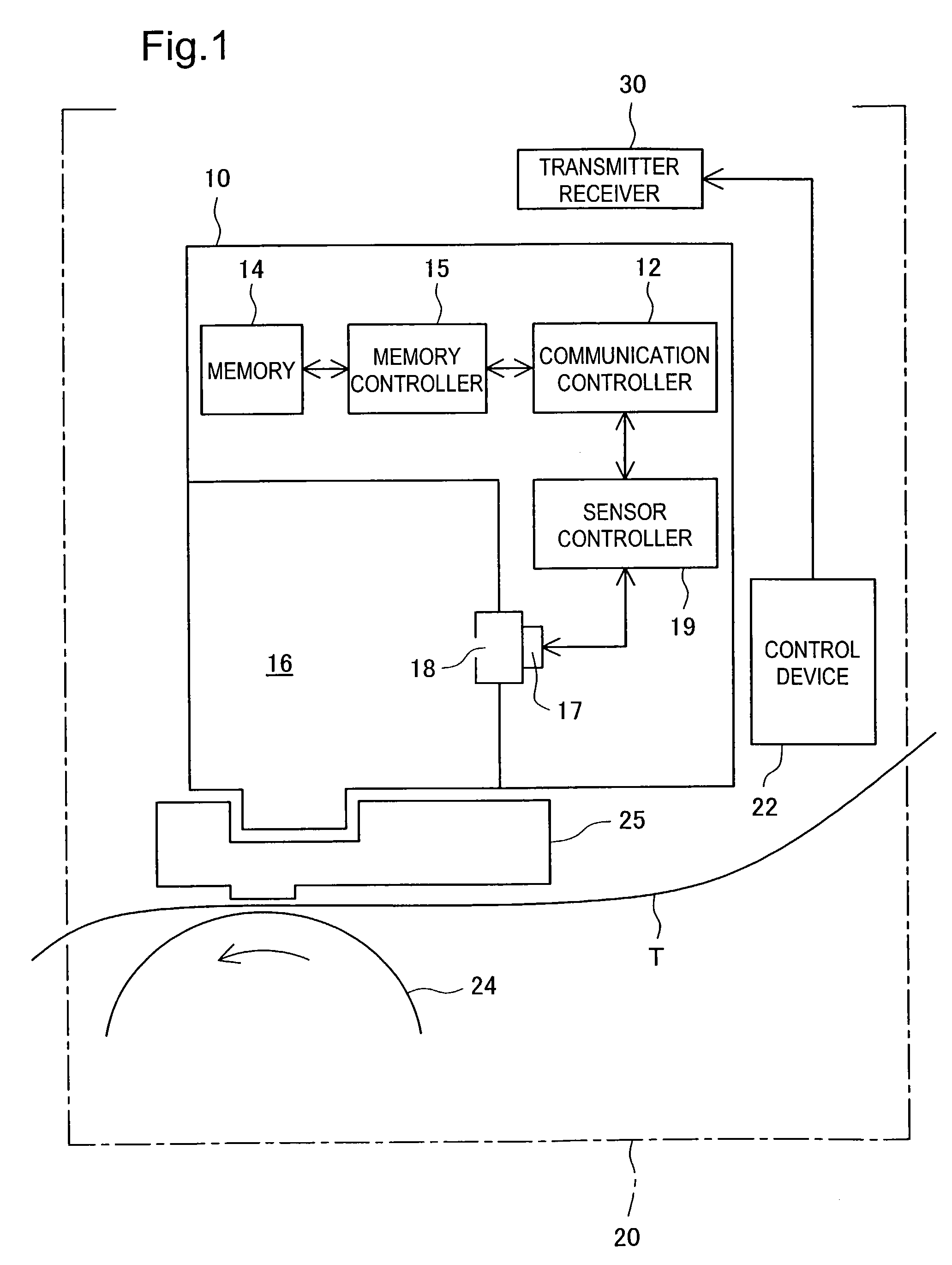
[0047]One mode of carrying out the invention is discussed below. FIG. 1 schematically illustrates the construction of an ink cartridge 10 and a transmitter receiver 30 of a printer 20, on which the ink cartridge 10 is mounted, in one mode of the present invention. The printer 20 causes ink to be ejected from a print head 25 onto a sheet of printing paper T fed by means of a platen 24. The internal structure of the printer 20 is not specifically illustrated or described here. A built-in control device 22 of the printer 20 computes the quantity of ink consumed for printing and other data and transmits the computed data to the ink cartridge 10 via the transmitter receiver 30. Transmission of data between the ink cartridge 10 and the control device 22 of the printer 20 is performed by radio communication in this mode, although the data transmission may alternatively be attained by cable communication. An electromagnetic induction method is applied for radio communication in this mode, b...


PUM


Abstract

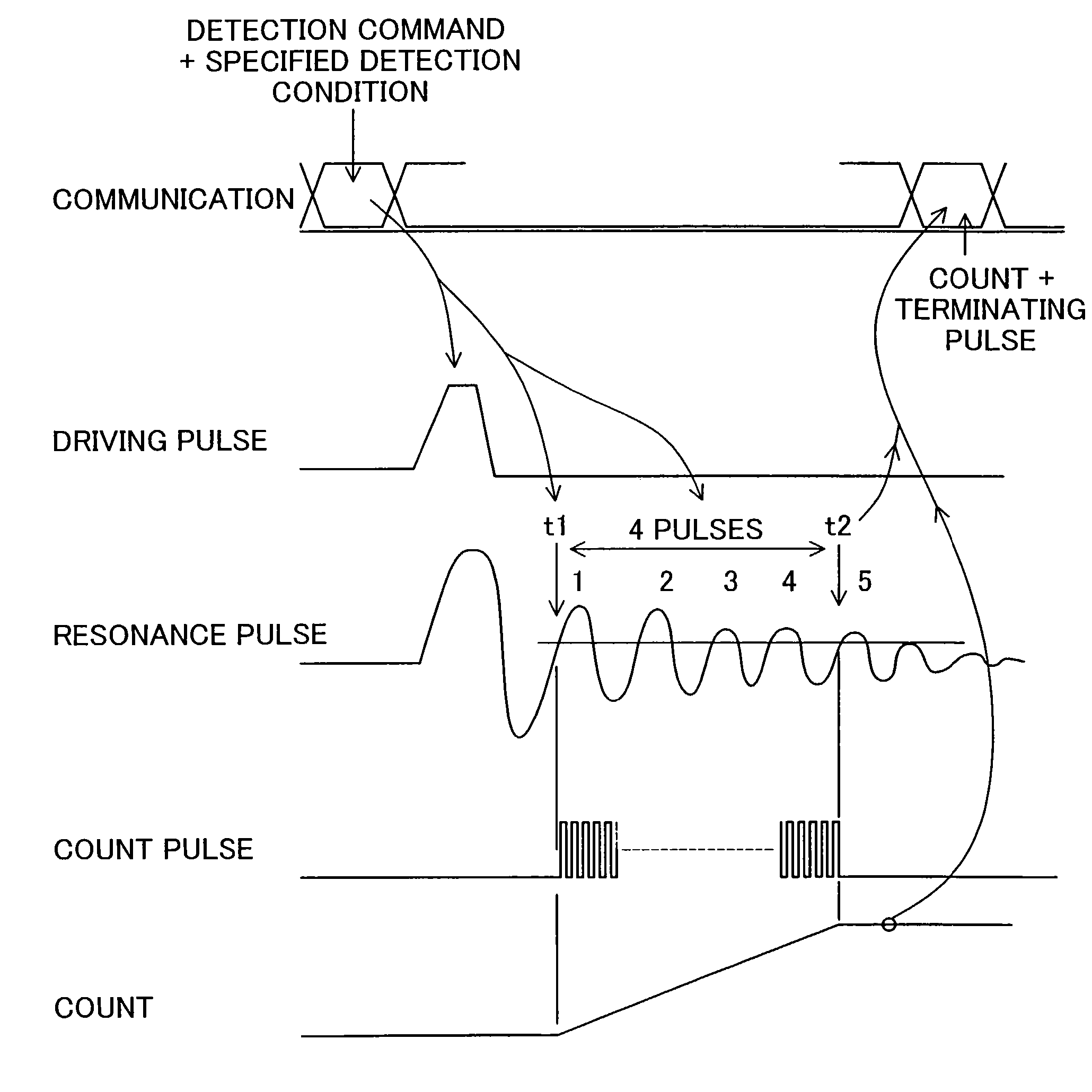
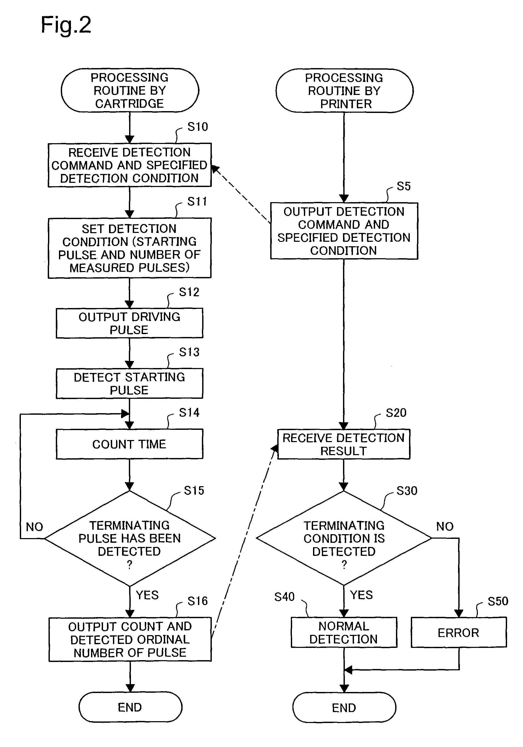
An ink cartridge has a sensor to detect ink. A printer's control device transmits a detection command and specified detection condition to the ink cartridge by radio communication. In response to input of the detection command into the ink cartridge, a sensor controller actuates and vibrates the sensor under the specified detection condition. The sensor is attached to a resonance chamber disposed in an ink chamber. The frequency of vibration of the sensor is regulated by a resonance frequency of the resonance chamber. The resonance frequency is varied by ink in the resonance chamber. Detection of the resonance frequency specifies if ink is in the resonance chamber and the remaining quantity of ink in the ink cartridge. The printer's control device receives the detection result together with the detection condition from the ink cartridge, and cheeks if detection was carried out under the specified detection condition, validate the detection result.

Description

BACKGROUND OF THE INVENTION[0001]1. Field of the Invention[0002]The present invention relates to a cartridge having a chamber to hold a recording material used for printing therein. More specifically the invention pertains to a technique of transmitting information between a cartridge with a built-in sensor and the cartridge with such a chamber.[0003]2. Description of the Related Art[0004]Various printers and printing apparatuses are widely used for printing; for example, printing apparatuses that eject inks onto printing paper for recording, such as ink jet printers, and printing apparatuses that use toners for printing. A cartridge set on such a printing apparatus has a chamber to hold a recording material like an ink or a toner therein. Management of the remaining quantity of the recording material is an important technique in the printing apparatus. While the printing apparatus counts and manages the consumed quantity by software, a proposed technique uses a sensor mounted on th...

Claims


Application Information

Patent Timeline
Patent Type & Authority Patents(United States)
IPC IPC(8): B41J29/393B41J2/17B41J2/175
CPCB41J2/17513B41J2/17566B41J2/17546B41J2002/17583B41J2/17
Inventor ASAUCHI, NOBORUKOSUGI, YASUHIKO
Owner SEIKO EPSON CORP
Learn More