Cap with underside light

a technology of underside light and cap, which is applied in the direction of electric lighting with batteries, lighting and heating equipment, lighting support devices, etc., can solve the problem of substantially unnoticeable light assembly

Inactive Publication Date: 2006-02-07
POMES NICK J
View PDF15 Cites 63 Cited by
  • Summary
  • Abstract
  • Description
  • Claims
  • Application Information

AI Technical Summary

Benefits of technology

[0014]It is another object of the invention to satisfy a need for a lighting device for a vari

Problems solved by technology

Such configuration renders the light assembly subst

Method used


Image

  • Cap with underside light
  • Cap with underside light
  • Cap with underside light

Examples


Embodiment Construction

[0036]Detailed descriptions of one or more preferred embodiments are provided herein. It is to be understood, however, that the present invention may be embodied in various forms. Therefore, specific details disclosed herein are not to be interpreted as limiting, but rather as a basis for the claims and as a representative basis for teaching one skilled in the art to employ the present invention in any appropriate system, structure or manner.

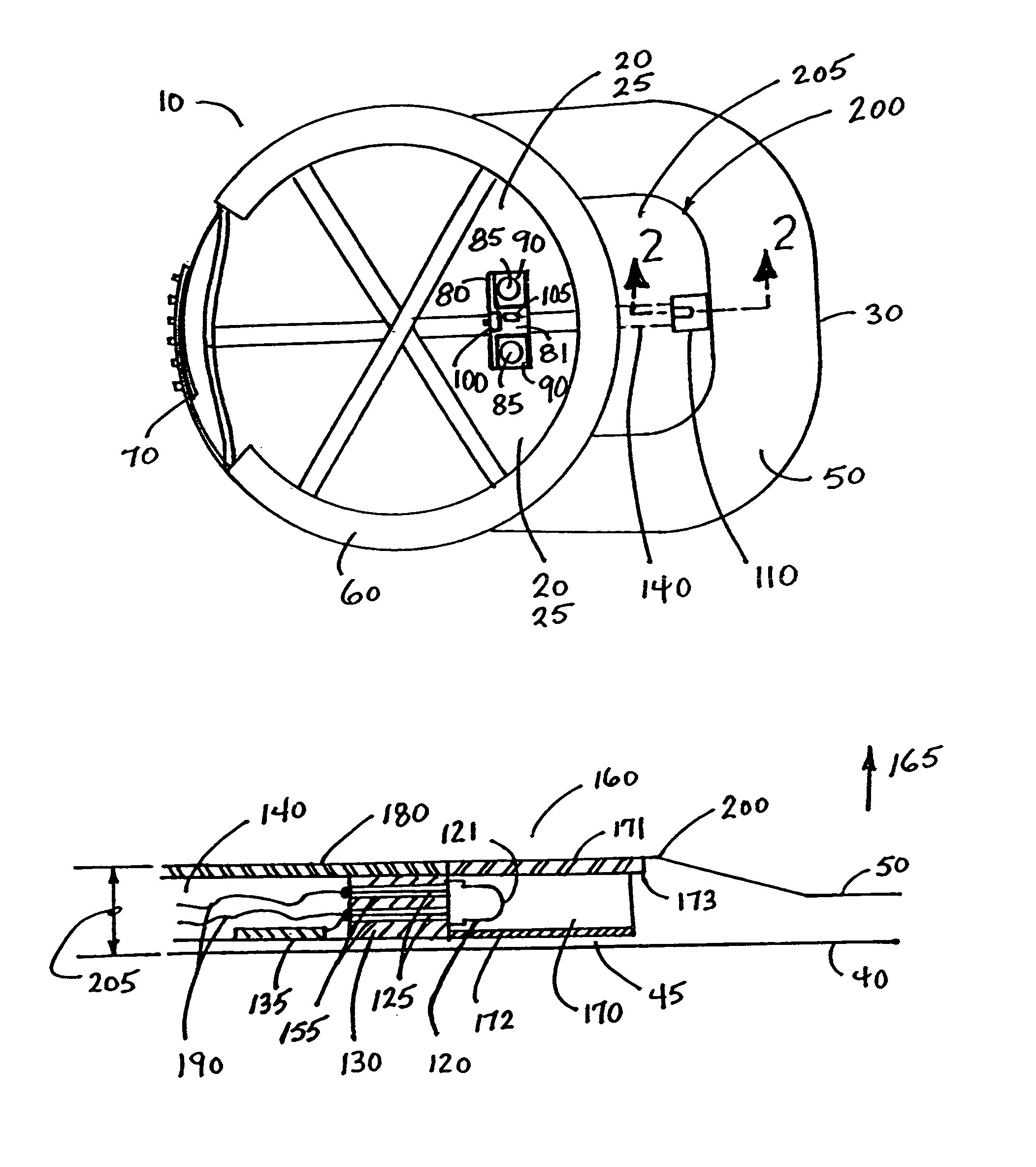
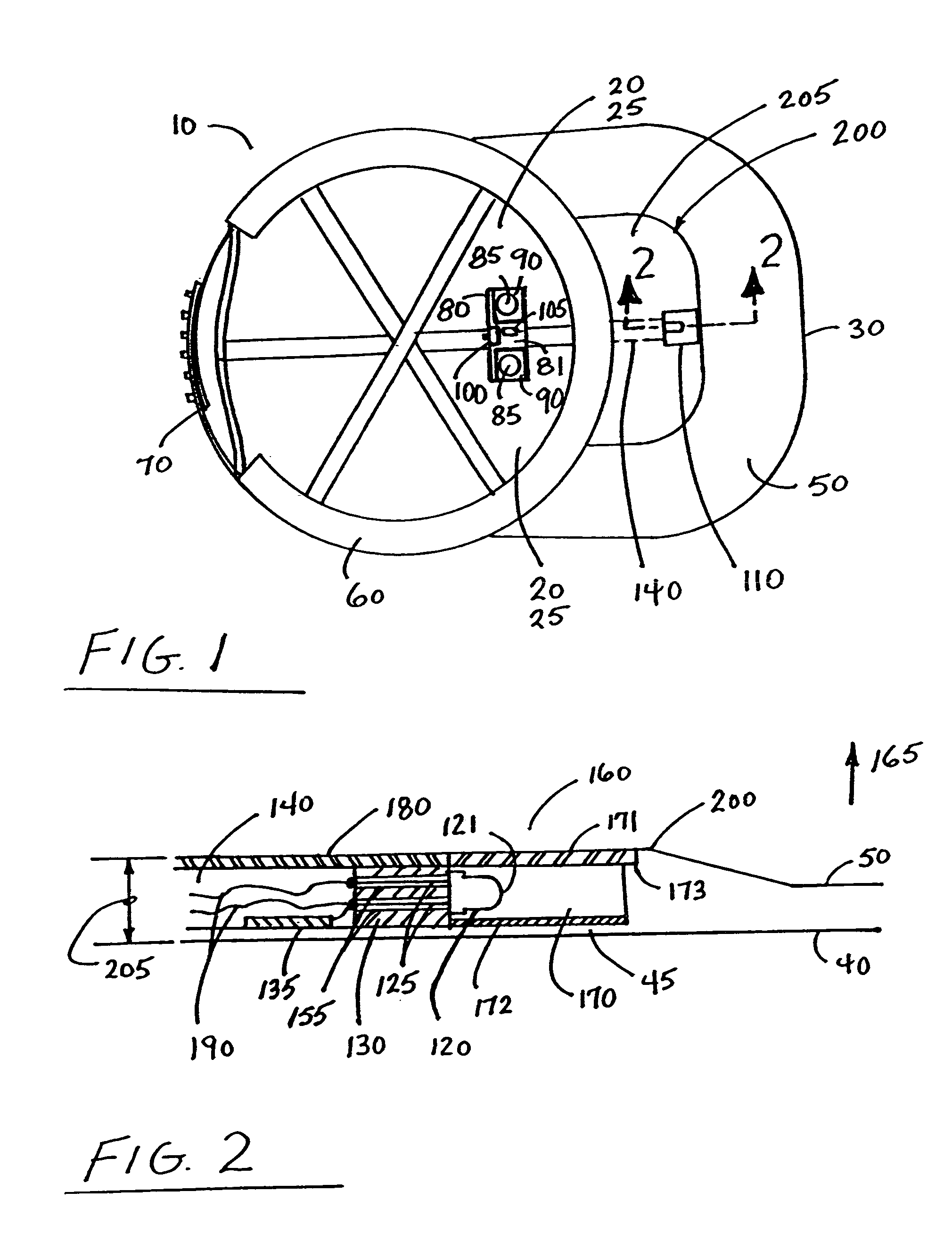
[0037]FIG. 1 is a bottom view of a baseball style cap 10 with light assembly 110. FIG. 1 illustrates the electrical component circuit board assembly with batteries 80 (referred to further herein simply as “battery assembly”) located inside the crown area 20 and separate from the light assembly 110. Three main parts of the apparatus can be seen:[0038](a) light assembly 110, (b) battery assembly 80 mounted inside crown 20, and (c) a formed recessed channel 140 for routing the interconnecting electrical wiring 190 between light assembly 110 and bat...


PUM


Abstract

A combination baseball or visor style cap and light assembly wherein in one embodiment the light assembly can be at least partially recessed in the underside of the bill so that the cap appears substantially unaltered in its aesthetic appearance. In one embodiment the light source can be a high intensity LED similar to those used in miniature flashlights and can be furnished in 3 mm or 5 mm size designations (however, any commercially available light source may be used).

Description

CROSS-REFERENCE TO RELATED APPLICATIONS[0001]Priority is hereby claimed to U.S. provisional patent application No. 60 / 423,305, filed Nov. 1, 2002.[0002]Priority is hereby claimed to U.S. provisional patent application No. 60 / 408,049, filed Sep. 4, 2002.[0003]U.S. provisional patent application No. 60 / 423,305, filed Nov. 1, 2002, is incorporated herein by reference.[0004]U.S. provisional patent application No. 60 / 408,049, filed Sep. 4, 2002, is incorporated herein by reference.STATEMENT REGARDING FEDERALLY SPONSORED RESEARCH OR DEVELOPMENT[0005]Not applicableREFERENCE TO A “MICROFICHE APPENDIX”[0006]Not applicableBACKGROUND[0007]1. Field[0008]This invention relates to lamps or lights mounted to caps. In one embodiment, this device relates to lamps or lights mounted to baseball type or visor type caps.[0009]2. General Background[0010]Prior art lights typically function by utilizing a bulky flashlight type apparatus that attach to cap bills with clips or are installed on the frontal cr...

Claims


Application Information

Patent Timeline
IPC IPC(8): F21V21/084
CPCA42B1/244A42B1/242
Inventor POMES, NICK J.
Owner POMES NICK J
Why Eureka
Try Eureka