Al technical title is built by PatSnap Al team. It summarizes the technical point description of the patent document.
a filter and filter technology, applied in the field of filter construction, can solve problems such as cost increas
Inactive Publication Date: 2006-02-07
DONALDSON CO INC
View PDF34 Cites 84 Cited by
Summary
Abstract
Description
Claims
Application Information
AI Technical Summary
This helps you quickly interpret patents by identifying the three key elements:
Problems solved by technology
Method used
Benefits of technology
Problems solved by technology
This caused an increase in cost.
Method used
Image
Click on the blue label to locate the original text in one second.
Reading with bidirectional positioning of images and text.
Examples
Embodiment Construction
[0026]A. FIG. 1, System of Use
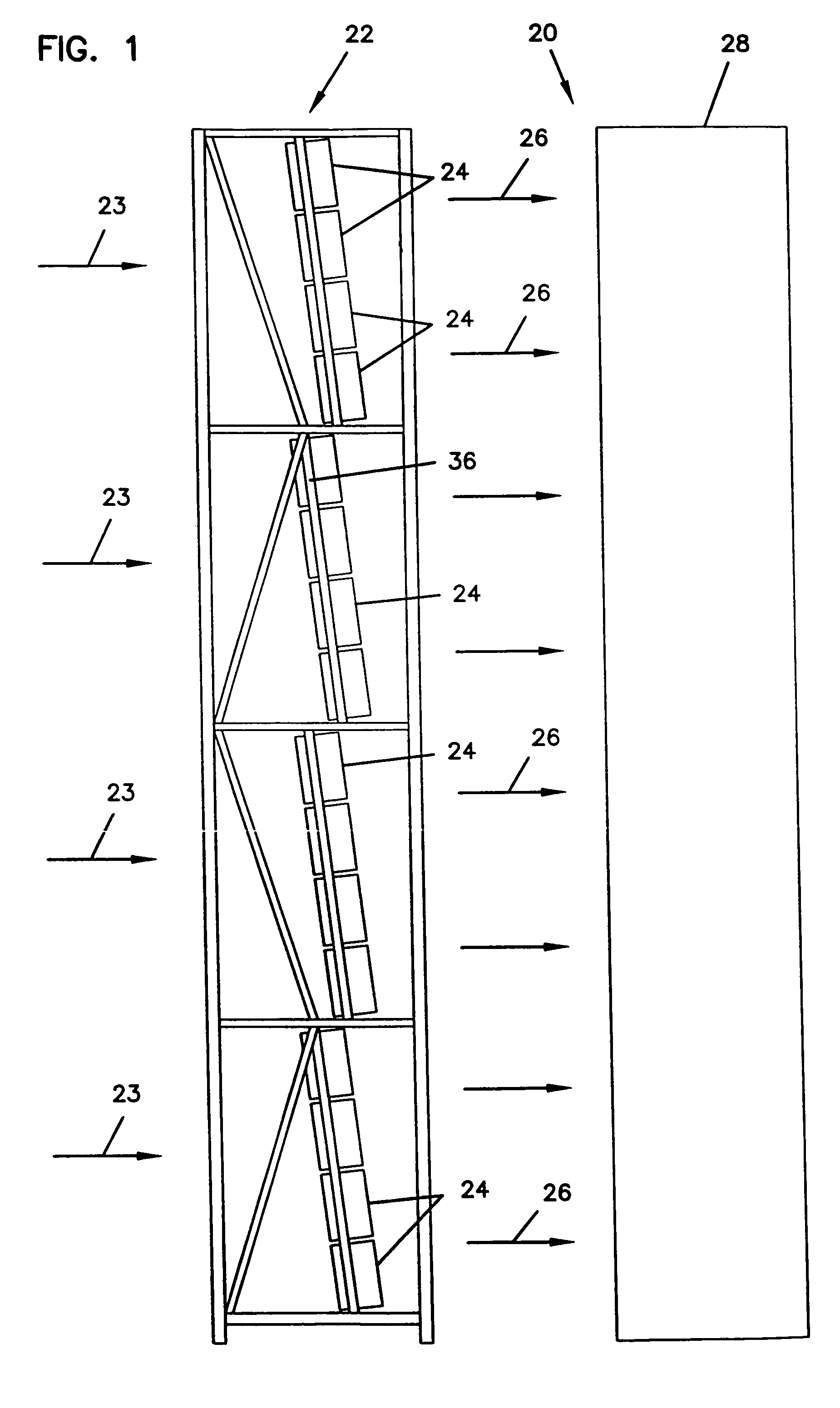
[0027]The air cleaner arrangements and constructions disclosed herein are usable in a variety of systems. FIG. 1 depicts one particular system, in this case, a gas turbine system schematically at 20.
[0028]In FIG. 1, airflow is shown drawn into an air intake system 22 at arrows 23. The air intake system 22 includes a plurality of air filter arrangements 24 generally held in a tube sheet 36. In preferred systems, the tube sheet 36 will be constructed to hold the filter arrangements 24 at an angle, relative to a vertical axis. Preferred angles will be between 5–25°, for example, about 7°. This permits liquid to drain from the filter arrangements 24 when the system 20 is not operating.
[0029]The air is cleaned in the air filter arrangements 24, and then it flows downstream at arrows 26 into gas turbine generator 28, where it is used to generate power.
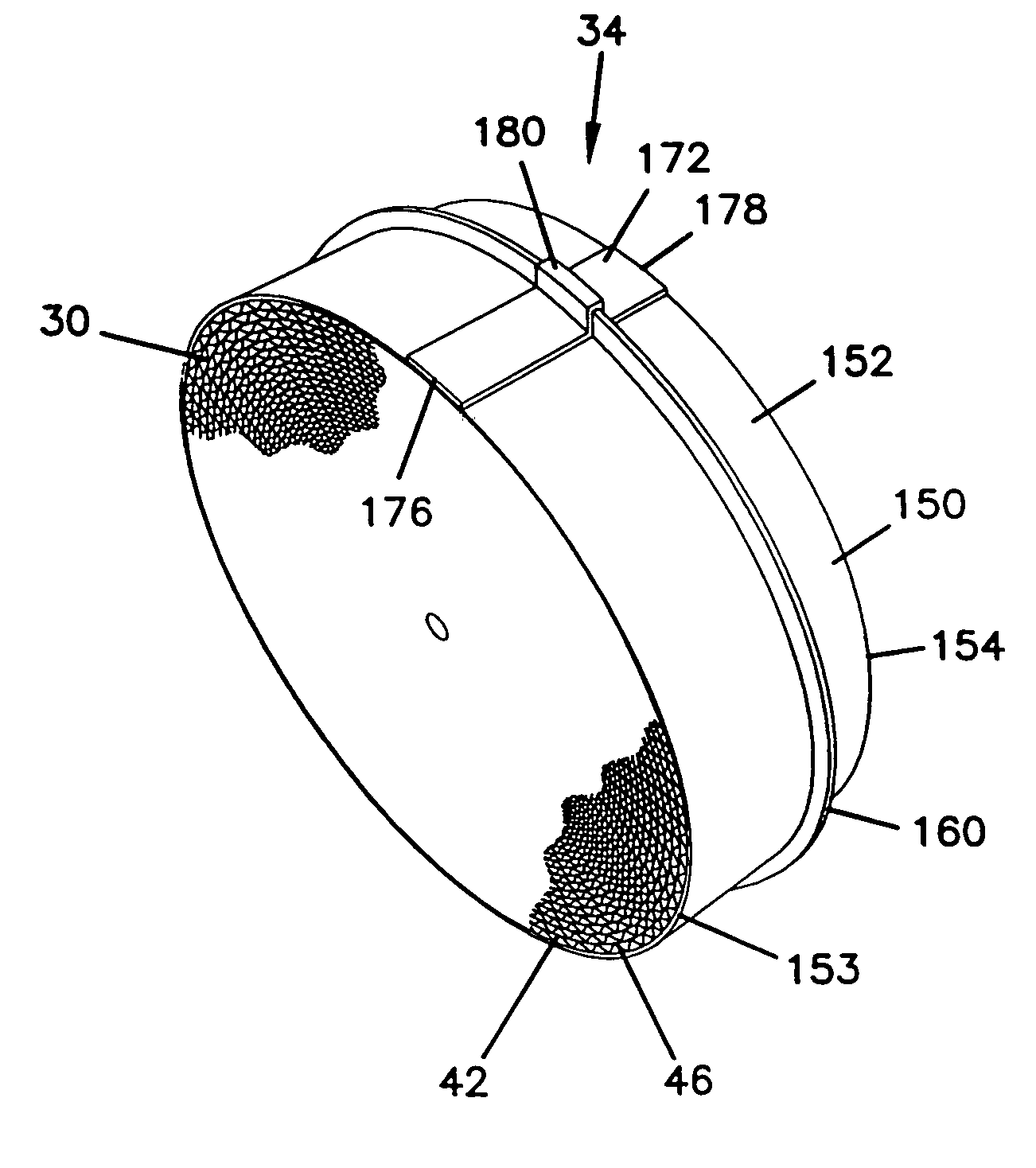
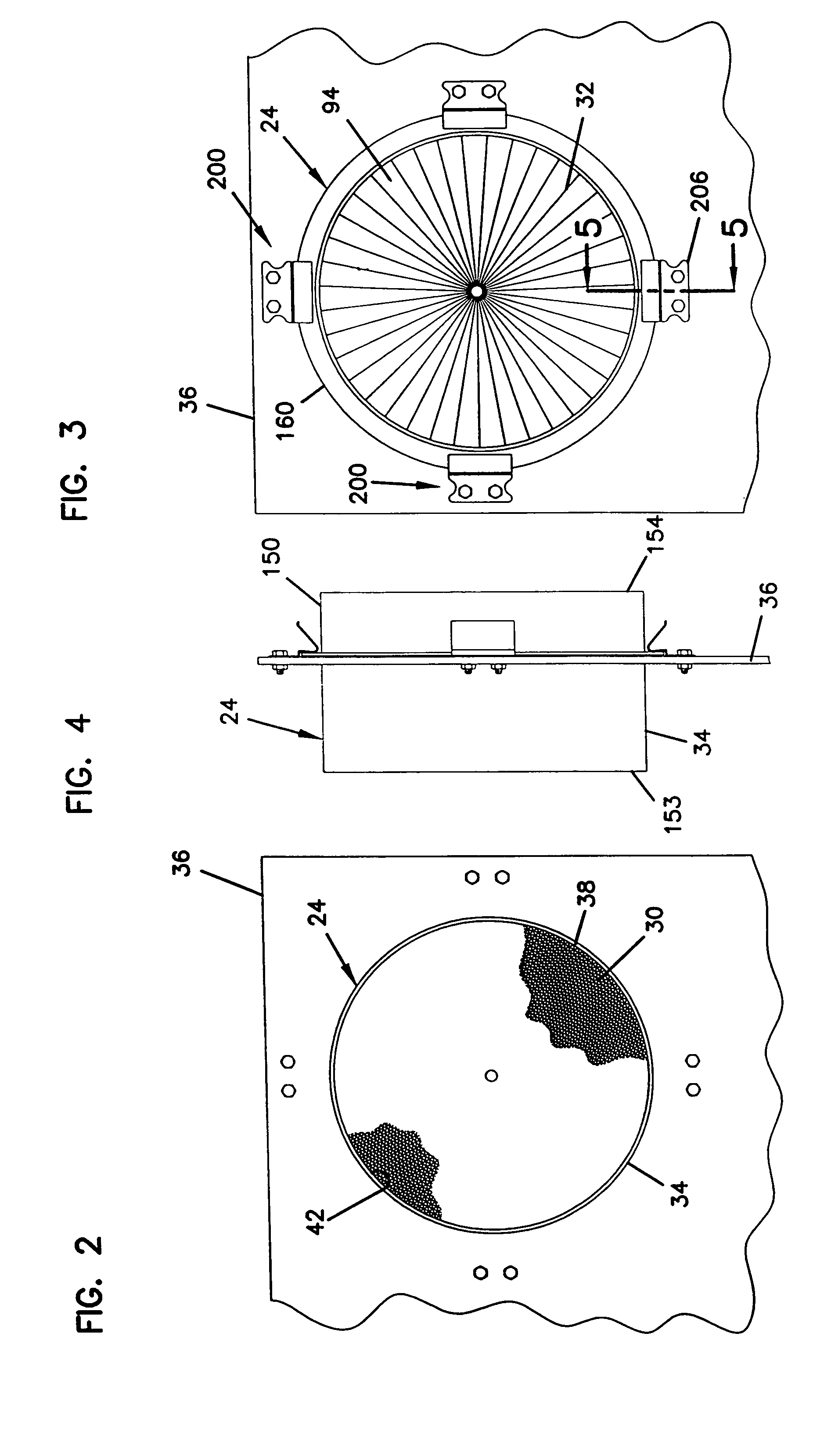
[0030]B. Overview of Air Filter Arrangement
[0031]One example of an air filter arrangement 24 usable in system...
PUM
Property
Measurement
Unit
distance
aaaaa
aaaaa
distance
aaaaa
aaaaa
diameter
aaaaa
aaaaa
Abstract
A filter arrangement includes a first filter element having opposite first and second ends; an axial length between the first and second ends; and a plurality of flutes. Each of the flutes has a first end portion adjacent to the first filter element first end, and a second end portion adjacent to the first filter element second end. Selected ones of the flutes are open at the first end potion and closed at the second end portion; and selected ones of the flutes are closed at the first end portion and open at the second end portion. A sleeve member secured to and circumscribing the first filter element. The sleeve member is oriented relative the first filter element to extend at least 30% of the axial length of the first filter element. A seal member pressure flange at least partially circumscribes the sleeve member. The filter arrangement is particularly useful for gas turbine systems. Methods for operating and servicing filter arrangements preferably utilize constructions herein.
Description
[0001]This application is a continuation of Application Ser. No. 10 / 382,250, filed Mar. 5, 2003, to issue as U.S. Pat. No. 6,960,245, on Nov. 1, 2005. Application Ser. No. 10 / 382,250 is a continuation of Application Ser. No. 10 / 077,513, filed Feb. 15, 2002, issued as U.S. Pat. No. 6,533,845 on Mar. 18, 2003. Application Ser. No. 10 / 077,513 is a continuation of Application Ser. No. 09 / 437,867, filed Nov. 10, 1999, issued as U.S. Pat. No. 6,348,085 on Feb. 19, 2002. Application Ser. Nos. 10 / 382,250, 10 / 077,513, and 09 / 437,867 are incorporated hereby by reference.TECHNICAL FIELD[0002]This disclosure describes filter constructions for filtering fluids, such as gas or liquid. In particular, this disclosure describes a filter element, a pre-filter, a housing, and methods particularly useful with gas turbine systems.BACKGROUND[0003]Gas turbine systems are useful in generating electricity. These types of systems are particularly convenient in that they can be constructed quickly; they are a...
Claims
Application Information
Patent Timeline
Application Date:The date an application was filed.
Publication Date:The date a patent or application was officially published.
First Publication Date:The earliest publication date of a patent with the same application number.
Issue Date:Publication date of the patent grant document.
PCT Entry Date:The Entry date of PCT National Phase.
Estimated Expiry Date:The statutory expiry date of a patent right according to the Patent Law, and it is the longest term of protection that the patent right can achieve without the termination of the patent right due to other reasons(Term extension factor has been taken into account ).
Invalid Date:Actual expiry date is based on effective date or publication date of legal transaction data of invalid patent.