System, method, and an article of manufacture for starting a brushless direct current motor

a direct current and motor technology, applied in the direction of motor/generator/converter stopper, electronic commutator, dynamo-electric converter control, etc., can solve the problems of not properly starting the motor at the customer site, time-consuming tuning/calibration process, and difficulty in detecting the rotor position of the motor control circui

Inactive Publication Date: 2006-02-07
INT BUSINESS MASCH CORP
View PDF16 Cites 42 Cited by
  • Summary
  • Abstract
  • Description
  • Claims
  • Application Information

AI Technical Summary

Problems solved by technology

Thus, motor control circuits have difficulty in detecting the rotor position when the rotor is not spinning or is spinning at low speeds.
The tuning / calibration process is a time-consuming process that requires an engineer to characterize motor start-up parameters, such as the duration and amplitude of each of the commutation pulses, that correlate to the acceleration characteristics of the motor / load combination.
However, if the motor torque, load, or applied voltage at a customer site varies substantially from those used during the tuning / calibration process, the preset start-up parameters (such as a pre-set commutation pulse duration or amplitude), may not properly start the motor at the customer site.

Method used


Image

  • System, method, and an article of manufacture for starting a brushless direct current motor
  • System, method, and an article of manufacture for starting a brushless direct current motor
  • System, method, and an article of manufacture for starting a brushless direct current motor

Examples


Embodiment Construction

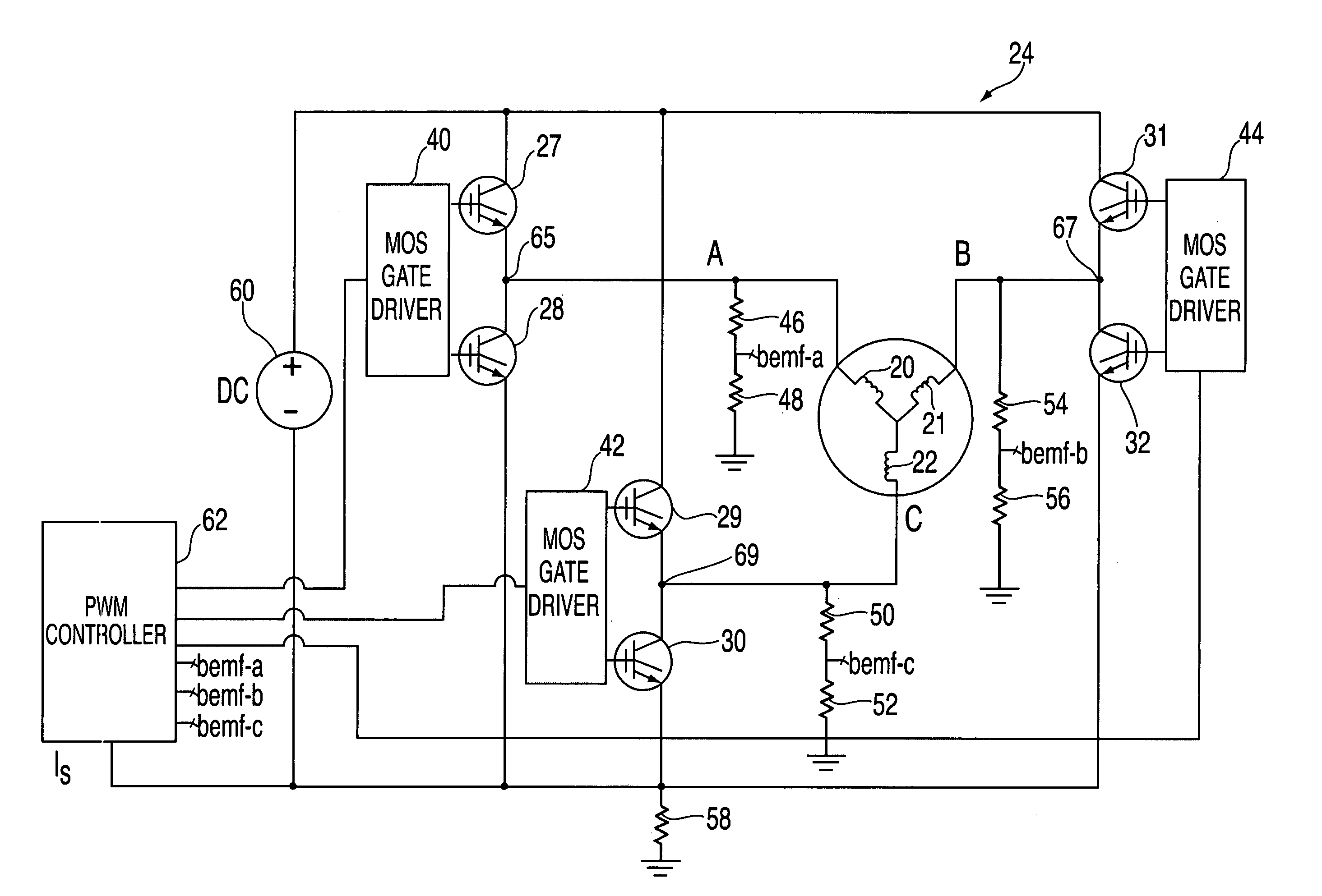
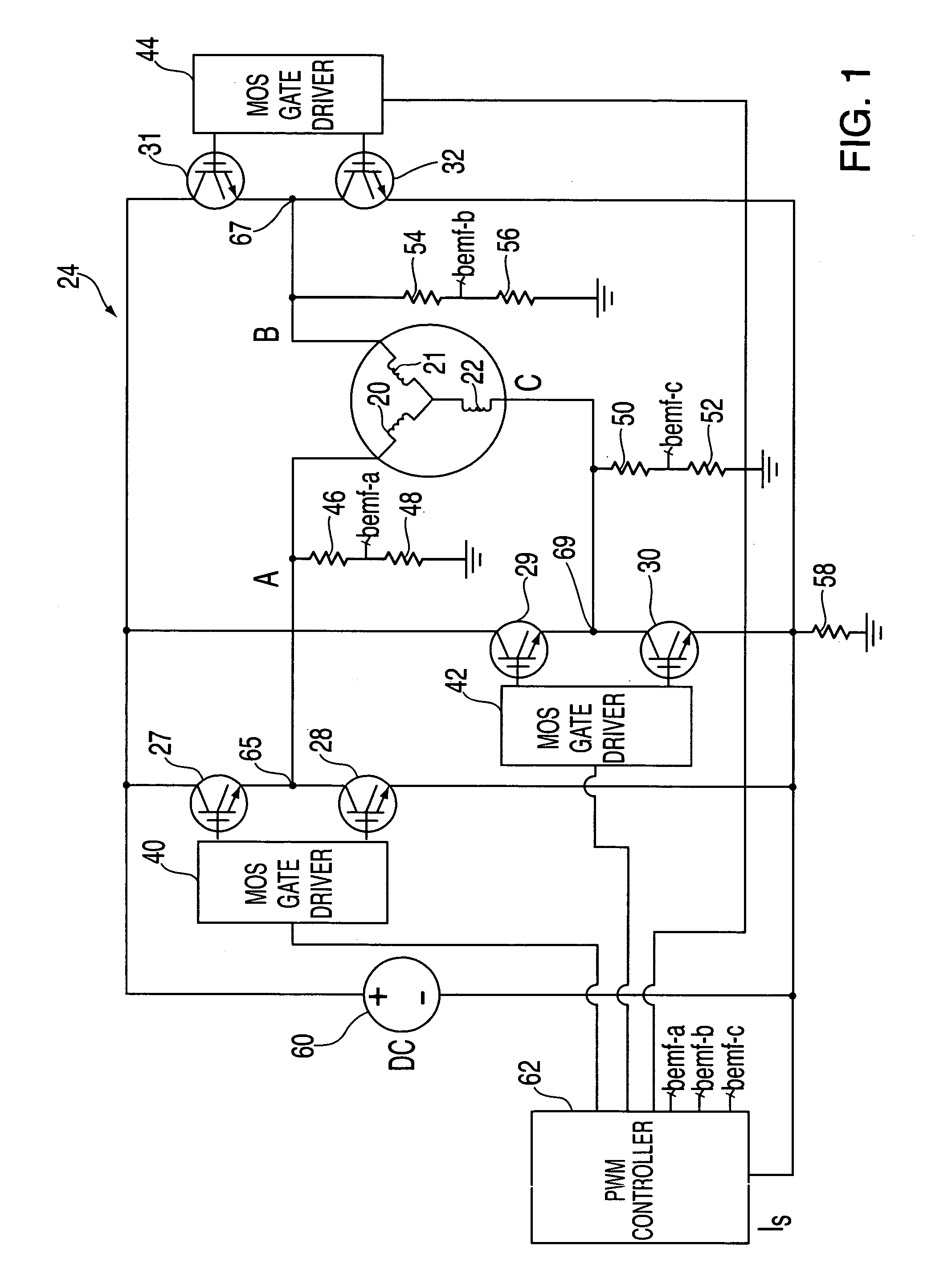
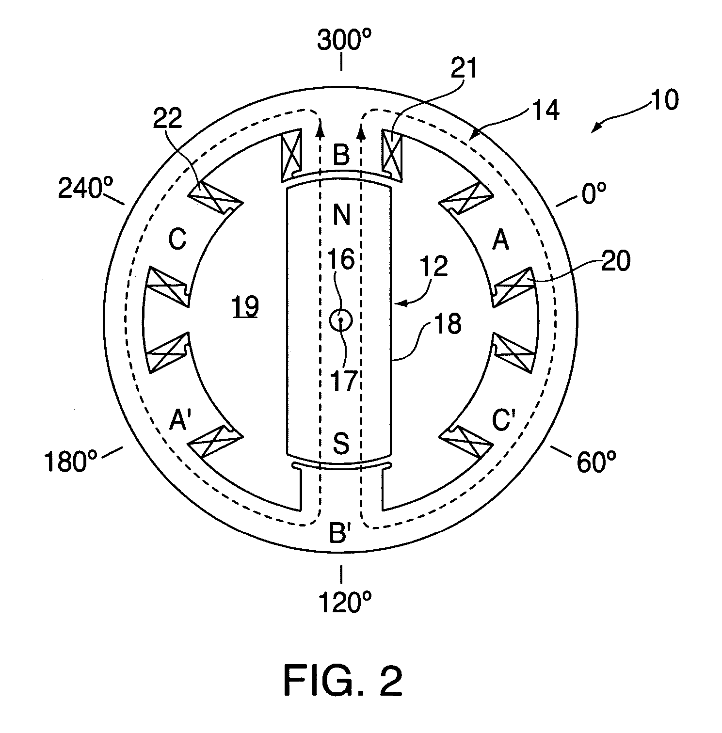
[0015]Referring to FIG. 2, a conventional sensorless brushless DC motor 10 is illustrated. Although the motor 10 comprises a brushless DC motor, it should be understood the invention disclosed herein could be applied to other motors known in the art. The motor 10 includes a rotor assembly 12 and a stator assembly 14 both of which may be centered about an axis 17. Although the illustrated embodiment includes three phase coils 20, 21, 22, it will be understood by those skilled in the art that the number of motor phase coils can vary.

[0016]The rotor assembly 12 is provided to move a load (not shown) connected to the rotor assembly 12. The rotor assembly 12 includes a shaft 16 and a rotor 18 disposed about the shaft 16. The shaft 16 is provided to engage either the load or other means for engaging the load. The shaft 16 extends longitudinally along axis 17 and may be centered about axis 17. The rotor 18 is provided to impart rotation to shaft 16 and is capable of clockwise or counterclo...


PUM


Abstract

A system and a method for starting a brushless DC motor are provided. The method includes applying commutation pulses to at least two phase coils to induce a rotor to rotate to a starting position and then de-energizing the at least two phase coils. The method further includes applying commutation pulses to at least two phase coils to induce the rotor to rotate from the starting position in a predetermined direction. The method further includes de-energizing all phase coils for a first time interval after the rotor is rotating and sampling a back EMF signal in at least one of the phase coils to determine a first value indicative of an electrical period of the back EMF signal or a portion of an electrical period of the back EMF signal. Finally, the method includes applying commutation pulses to at least two phase coils for a second time interval, the second time interval being based on the first value.

Description

FIELD OF INVENTION[0001]The invention relates to a system, method, and an article of manufacture for starting a brushless direct current (DC) motor.BACKGROUND OF INVENTION[0002]Brushless sensorless DC motors have been used extensively to power devices such as blowers. In order to start a brushless sensorless DC motor, a calibrated sequence of commutation pulses must be applied to phase coils in the motor. These commutation pulses increase at a frequency rate that closely matches the rate at which a rotor of the motor accelerates to start and maintain a rotation of the rotor.[0003]Brushless sensorless DC motors generally utilize back electromotive force (EMF) signals generated in the phase coils to determine the rotor position. Each of the back EMF signals has an amplitude that varies linearly with motor speed and has a zero value when a rotor is not rotating or is rotating at low speeds. Thus, motor control circuits have difficulty in detecting the rotor position when the rotor is n...

Claims


Application Information

Patent Timeline
Patent Type & Authority Patents(United States)
IPC IPC(8): H02P3/18H02P1/46H02P6/18
CPCH02P6/185
Inventor BIAMONTE, JEFFREY R.HARRINGTON, RAYMOND J.TRIFILO, TIMOTHY
Owner INT BUSINESS MASCH CORP
Why Eureka
Try Eureka