
Method of simultaneously reading multiple radio frequency tags, RF tags, and RF reader

a radio frequency identification and reader technology, applied in the field of radio frequency identification tags, can solve the problems of inability to perform sequential polling, time required to perform radio frequency identification scanning under established methods,

Inactive Publication Date: 2006-02-07
BATTELLE MEMORIAL INST
View PDF33 Cites 112 Cited by
  • Summary
  • Abstract
  • Description
  • Claims
  • Application Information

AI Technical Summary

Benefits of technology

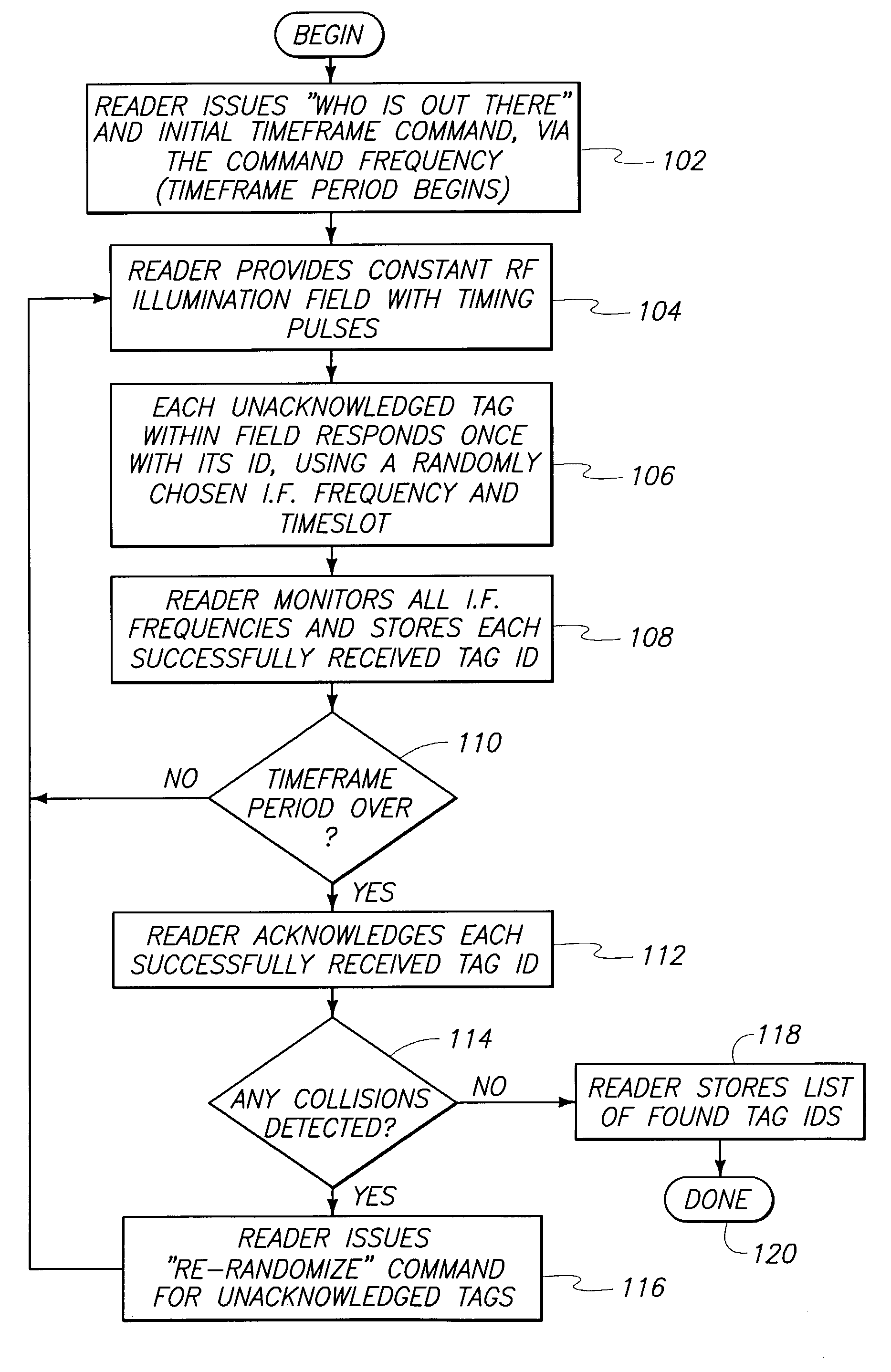
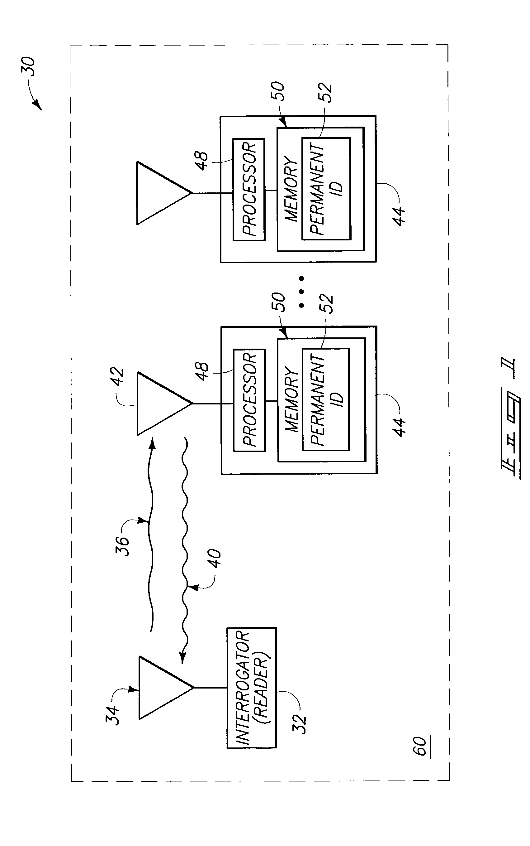
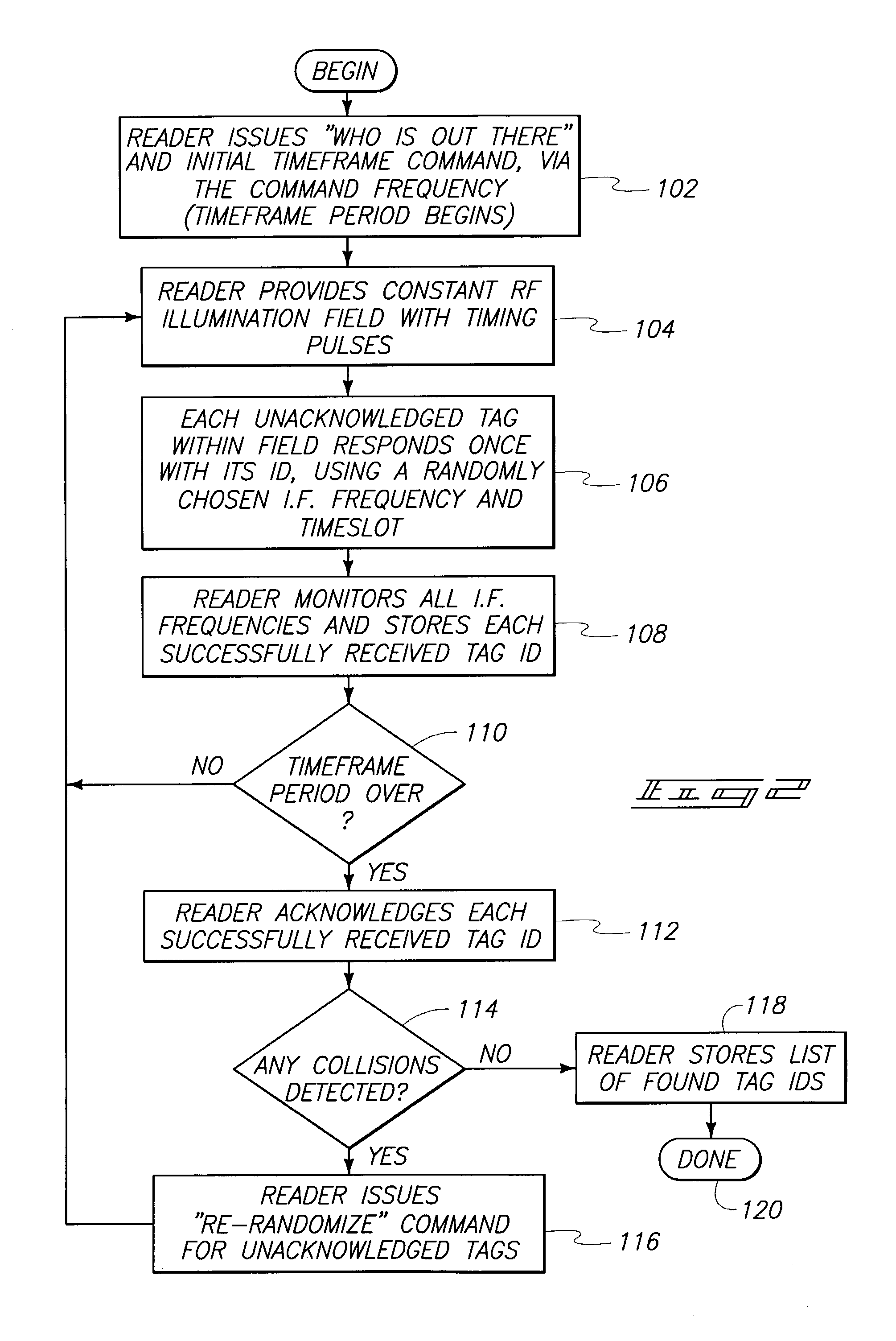
The invention provides a method for identifying RF tags using a reader and a continuous RF illumination field. The reader issues a wireless command to RF tags, requesting them to identify themselves, and the tags randomly select a radio frequency and timeslot to respond. The reader receives the wireless responses and issues wireless acknowledgements to successfully identified RF tags. The invention also provides a radio frequency identification system comprising an RF reader and a plurality of RF tags. The RF tags include circuitry to select a frequency and timeslot to respond to the reader's discovery command, and the reader provides a time synchronization signal and simultaneously monitors a plurality of frequencies to receive the RF tag's identification data. The technical effects of the invention include improved identification accuracy and efficiency of RF tags in RFID systems.

Problems solved by technology

The time required to perform this scanning under established methods can be formidable, in view of the quantity of tags to be scanned and recorded.
What is needed is a system and method for expeditious, automatic scanning and identification of a plurality of RF tags within the working proximity of a reader, such as in scenarios where the reader does not know the identities of the tags present in the field and sequential polling is therefore not an option.

Method used


Image

  • Method of simultaneously reading multiple radio frequency tags, RF tags, and RF reader
  • Method of simultaneously reading multiple radio frequency tags, RF tags, and RF reader
  • Method of simultaneously reading multiple radio frequency tags, RF tags, and RF reader

Examples


Embodiment Construction

[0020]Attention is directed to the following commonly assigned applications, which are incorporated herein by reference: U.S. Patent Application Ser. No. 10 / 263,826 entitled “Radio Frequency Identification Device Communication Systems, Wireless Communication Devices, Backscatter Communication Methods and Radio Frequency Identification Device Communication Methods” by inventors Mike A. Hughes and Richard M. Pratt; U.S. Patent Application Ser. No. 10 / 2263,873, entitled “RFID System and Method Including Tag ID Compression”, by inventors Mike A. Hughes and Richard M. Pratt; U.S. Patent Application Ser. No. 10 / 264,078, entitled “System and Method to Identify Multiple RFID Tags”, by inventors Mike A. Hughes and Richard M. Pratt; U.S. Patent Application Ser. No. 10 / 263,940, entitled “Wireless Communication Devices, Radio Frequency Identification Devices, Backscatter Communication Device Wake-Up Methods and Radio Frequency Identification Device Wake-Up Methods”, by inventors Richard Pratt a...


PUM


Abstract

An RF tag system, comprising an RF reader configured to issue a plurality of different RF commands and to provide a continuous RF illumination field, and a plurality of RF tags respectively including a permanent identification; wherein the plurality of RF tags are configured to respond to a certain RF command from the RF reader by transmitting their respective identifications by way of backscatter modulation of the RF illumination field, and wherein the RF tags are further configured to perform the responding by way of respective independently selected random radio frequencies and timeslots from respective pre-defined ranges of radio frequencies and timeslots.

Description

TECHNICAL FIELD[0001]The invention relates to radio frequency identification tags. More particularly, the invention relates to a system and method of identifying radio frequency identification tags within an area.BACKGROUND OF THE INVENTION[0002]Radio frequency identification tags (RF tags) are utilized in a wide variety of applications: inventory control; tracking personnel within a facility; secured access control; locating stored articles; etc. As business and industry become more dependant upon RF tagging, the population of tags within a given area or facility increases correspondingly.[0003]For example, the arrival of a large quantity of inventory at a storage facility can introduce a proportionate number of individual RF tags (each including a unique identification, as well as other possible data) which require scanning so as to be recorded in the relevant database. The time required to perform this scanning under established methods can be formidable, in view of the quantity ...

Claims


Application Information

Patent Timeline
Patent Type & Authority Patents(United States)
IPC IPC(8): H04Q5/22H04B7/212H04L12/43G06K7/00G06K19/07
CPCG06K7/0008G06K19/0723G06K7/10069G06K7/10059
Inventor ERTIN, EMREPRATT, RICHARD M.HUGHES, MICHAEL A.PRIDDY, KEVIN L.LECHELT, WAYNE M.
Owner BATTELLE MEMORIAL INST
Learn More