Apparatus for controlling a screen pointer with a frame rate based on velocity

a technology of velocity and apparatus, applied in static indicating devices, instruments, sustainable buildings, etc., can solve the problems of excessive power consumption of optical pointing devices, power consumption of large amount, and excessive power consumption of tracking these slower movements at a high frame ra

Active Publication Date: 2006-02-07
ELAN MICROELECTRONICS CORPORATION
View PDF12 Cites 171 Cited by
  • Summary
  • Abstract
  • Description
  • Claims
  • Application Information

AI Technical Summary

Problems solved by technology

One major source of power drain in optical pointing devices is the light source typically used in these devices.
However, the majority of mouse movements are not at high velocities, and slower movements can be accurately tracked at a slower frame rate.
Excess power is consumed by tracking these slower movements at a high frame rate.
A relatively significant amount of power is consumed by digitizing and processing these full frames to determine whether any motion has occurred.

Method used


Image

  • Apparatus for controlling a screen pointer with a frame rate based on velocity
  • Apparatus for controlling a screen pointer with a frame rate based on velocity
  • Apparatus for controlling a screen pointer with a frame rate based on velocity

Examples


Embodiment Construction

[0015]In the following detailed description of the preferred embodiments, reference is made to the accompanying drawings, which form a part hereof, and in which is shown by way of illustration specific embodiments in which the invention may be practiced. It is to be understood that other embodiments may be utilized and structural or logical changes may be made without departing from the scope of the present invention. The following detailed description, therefore, is not to be taken in a limiting sense, and the scope of the present invention is defined by the appended claims.

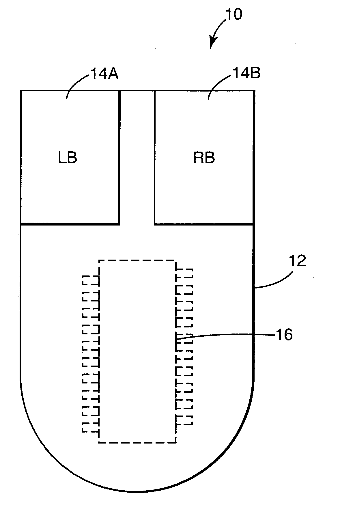
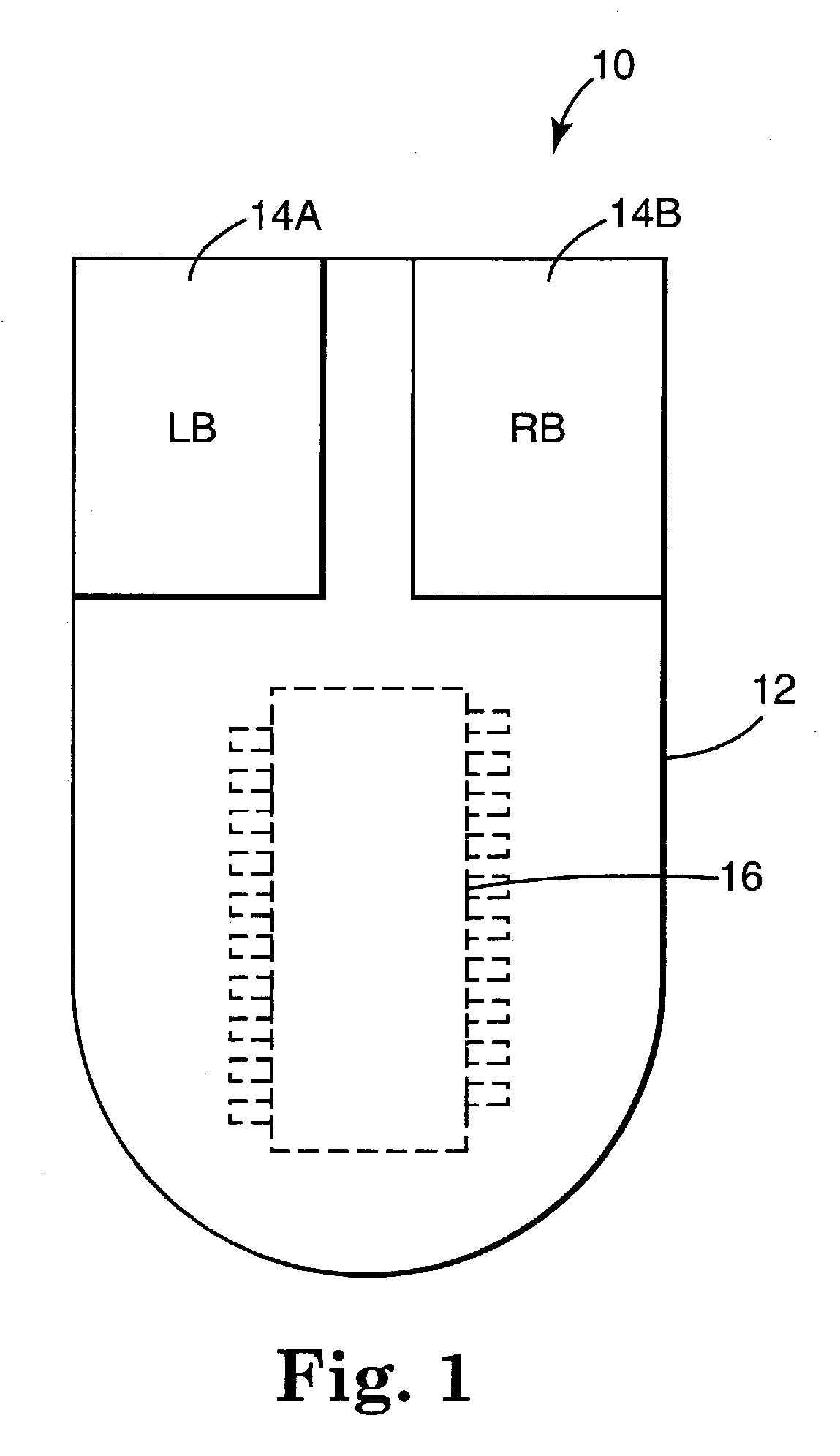
[0016]FIG. 1 is a top view of an optical mouse 10 according to one embodiment of the present invention. Mouse 10 includes plastic case 12, left mouse button (LB) 14A, right mouse button (RB) 14B, and optical motion sensor chip 16. Sensor chip 16 is covered by plastic case 12, and is therefore shown with dashed lines in FIG. 1.

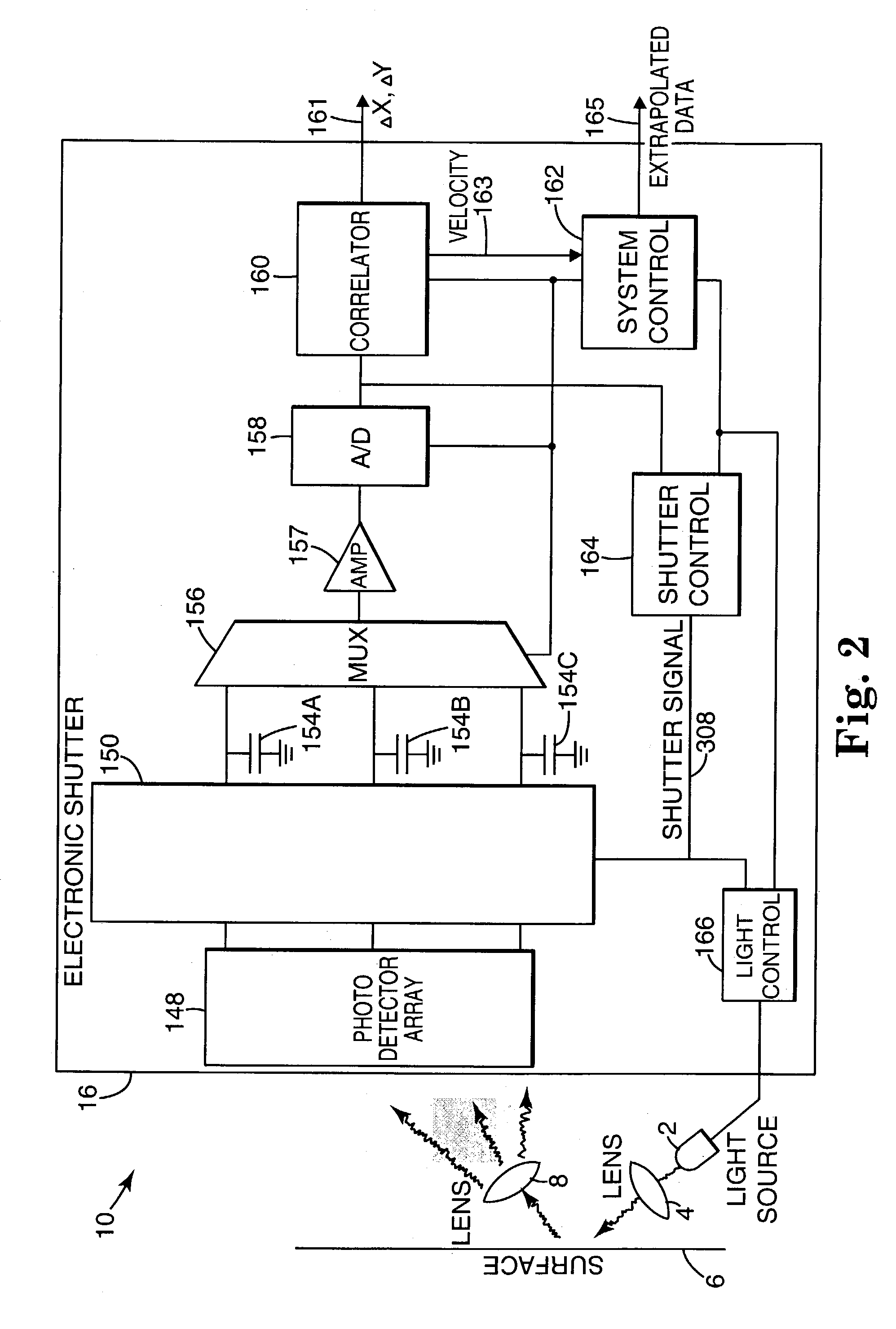
[0017]FIG. 2 is a block diagram illustrating major components of optical mouse 10 accor...


PUM


Abstract

An apparatus for controlling the position of a screen pointer for an electronic device having a display screen includes a light source for illuminating an imaging surface, thereby generating reflected images. An optical motion sensor generates digital images from the reflected images at a first frame rate. The motion sensor is configured to generate movement data based on the digital images. The movement data is indicative of relative motion between the imaging surface and the apparatus. The motion sensor is configured to modify the first frame rate to one of a plurality of alternate frame rates based on a current relative velocity between the imaging surface and the apparatus.

Description

THE FIELD OF THE INVENTION[0001]This invention relates generally to devices for controlling a pointer on a display screen, and relates more particularly to an apparatus for controlling a screen pointer with a frame rate based on velocity.BACKGROUND OF THE INVENTION[0002]The use of a hand operated pointing device for use with a computer and its display has become almost universal. One form of the various types of pointing devices is the conventional (mechanical) mouse, used in conjunction with a cooperating mouse pad. Mechanical mice typically include a rubber-surfaced steel ball that rolls over the mouse pad as the mouse is moved. Interior to the mouse are rollers, or wheels, that contact the ball at its equator and convert its rotation into electrical signals representing orthogonal components of mouse motion. These electrical signals are coupled to a computer, where software responds to the signals to change by a ΔX and a ΔY the displayed position of a pointer (cursor) in accordan...

Claims


Application Information

Patent Timeline
Patent Type & Authority Patents(United States)
IPC IPC(8): G09G5/08G06F1/32G06F3/03G06F3/038G06T7/20
CPCG06F1/3203G06F1/3259G06F3/0317G06F3/03547G06T7/20G06F3/038Y02B60/148G06F2203/0338Y02B60/1253Y02D10/00
Inventor GORDON, GARY B.BROSNAN, MICHAEL J.
Owner ELAN MICROELECTRONICS CORPORATION
Why Eureka
Try Eureka